Figures from Null & Lobur
Chapter 1: Data Representation
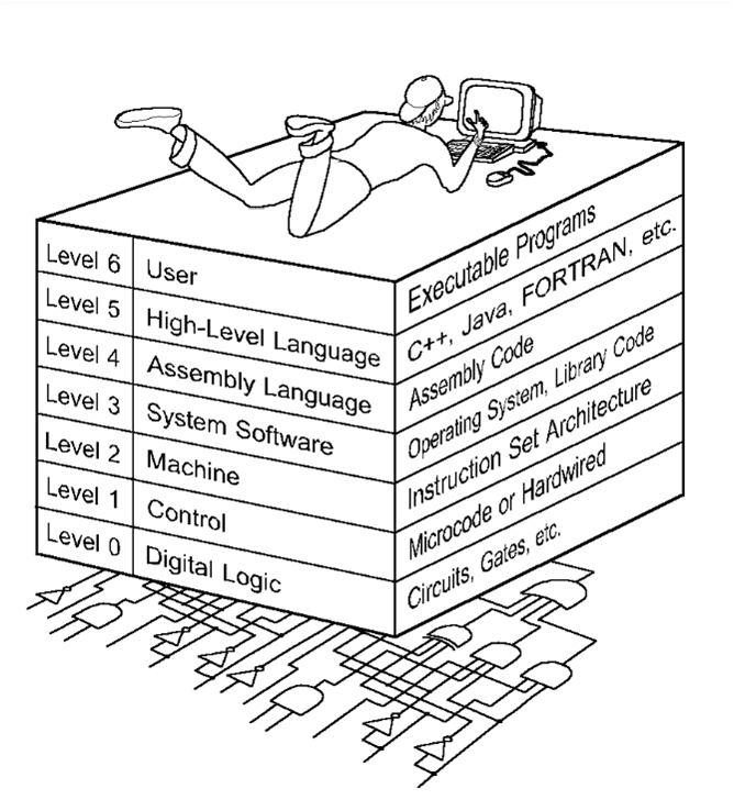
Figure 1.3 The Abstract Levels of Modern Computing Systems
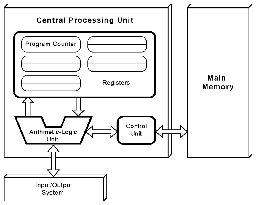
Figure 1.4 The Von Neumann Architecture
Chapter 2: Data Representation
Table 2.2 Carry and Overflow
Table 2.3 Error Propagation
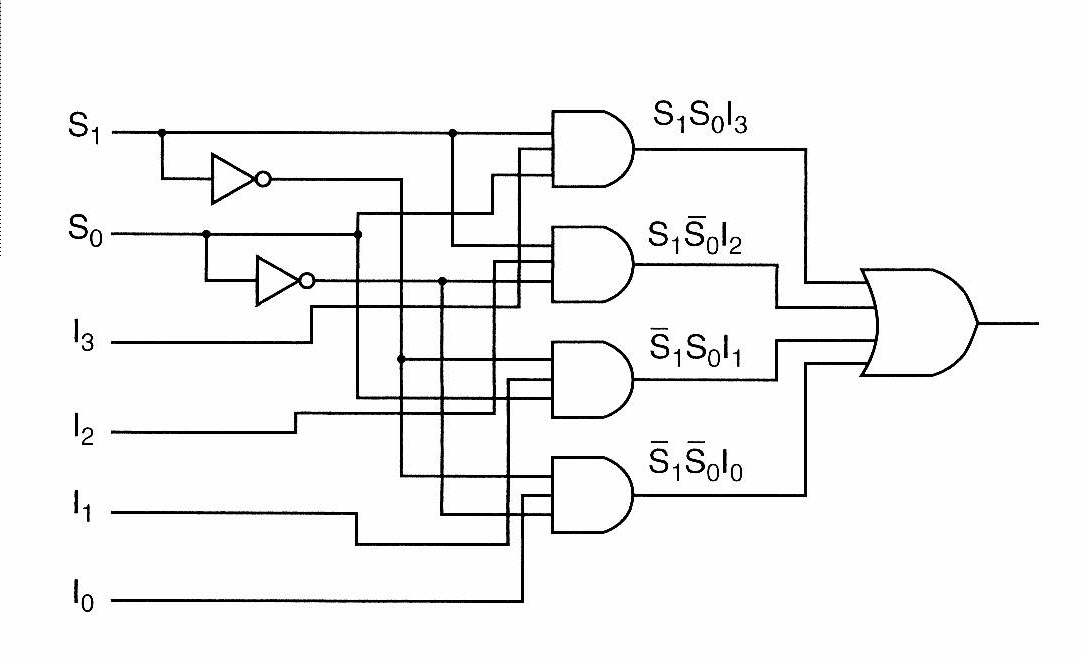
Chapter 3: Circuit Diagrams
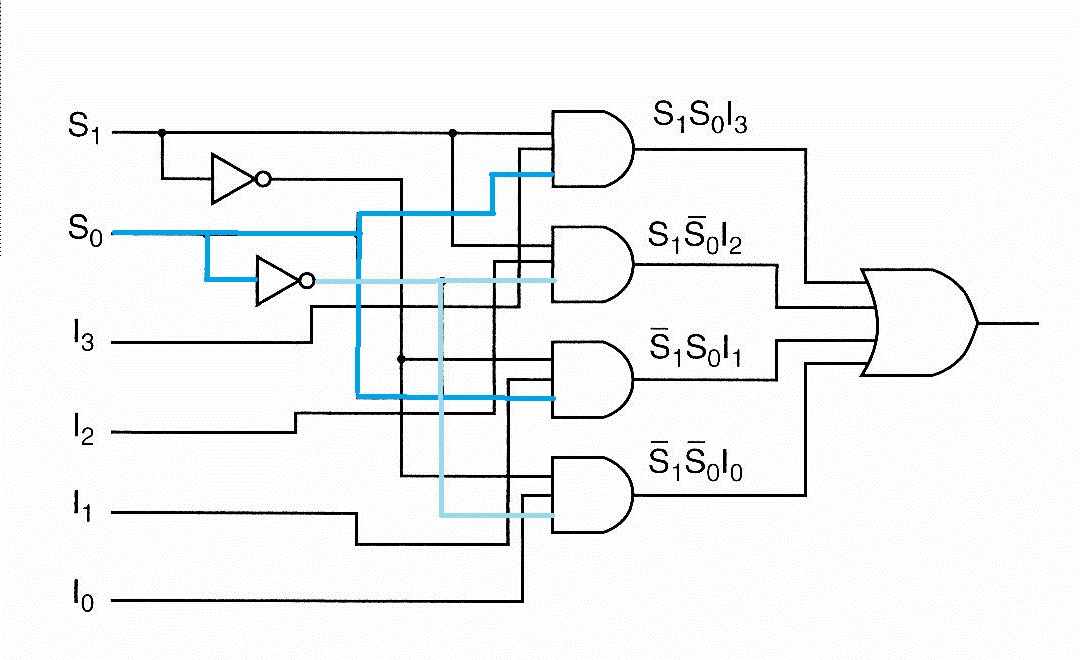
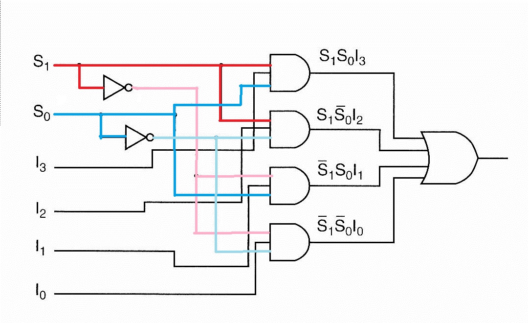
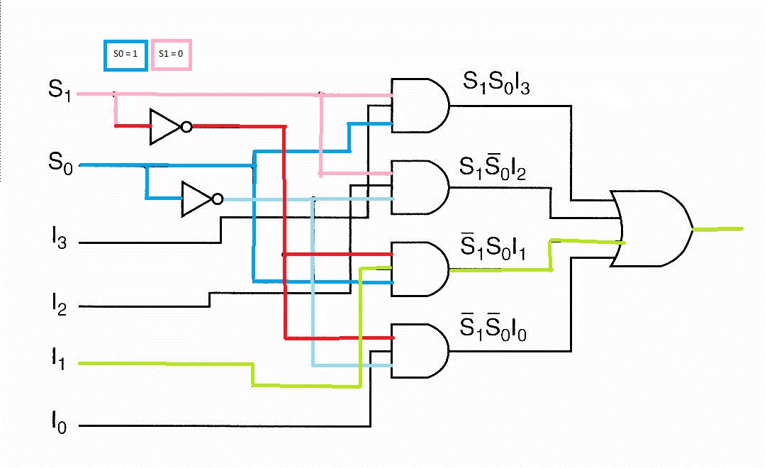
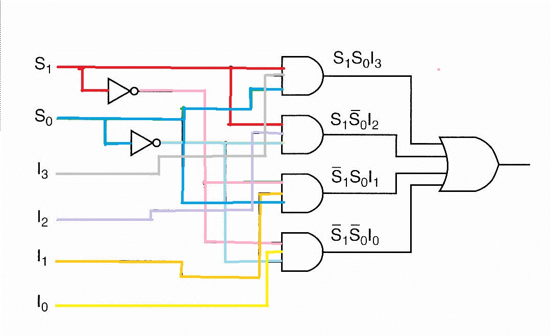
multiplexer
multiplexer_S1
multiplexer_S0
multiplexer_S1andS0
multiplexer_select_Input1
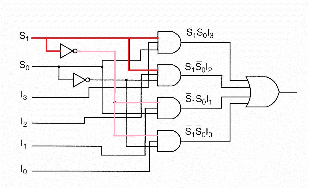
color_coded_multiplexer
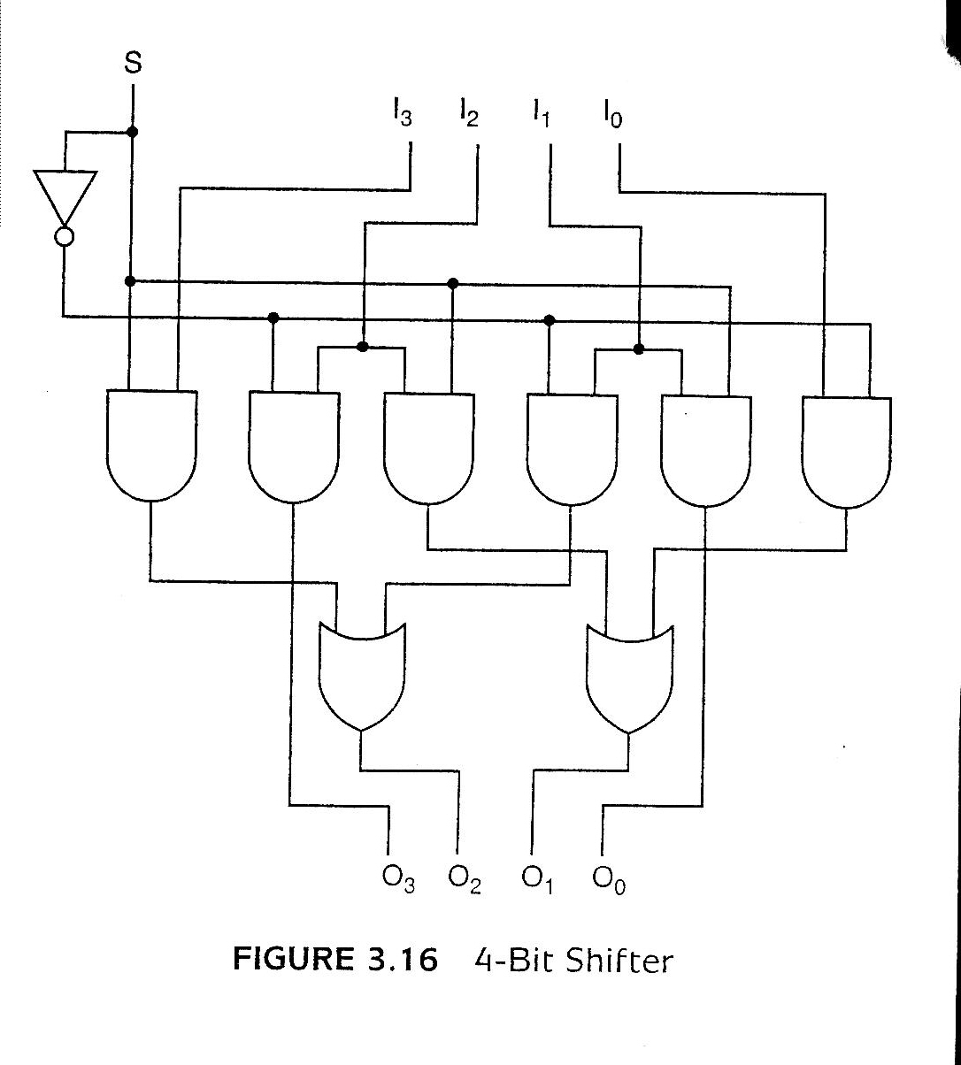
Figure 3.16 4-bit shifter
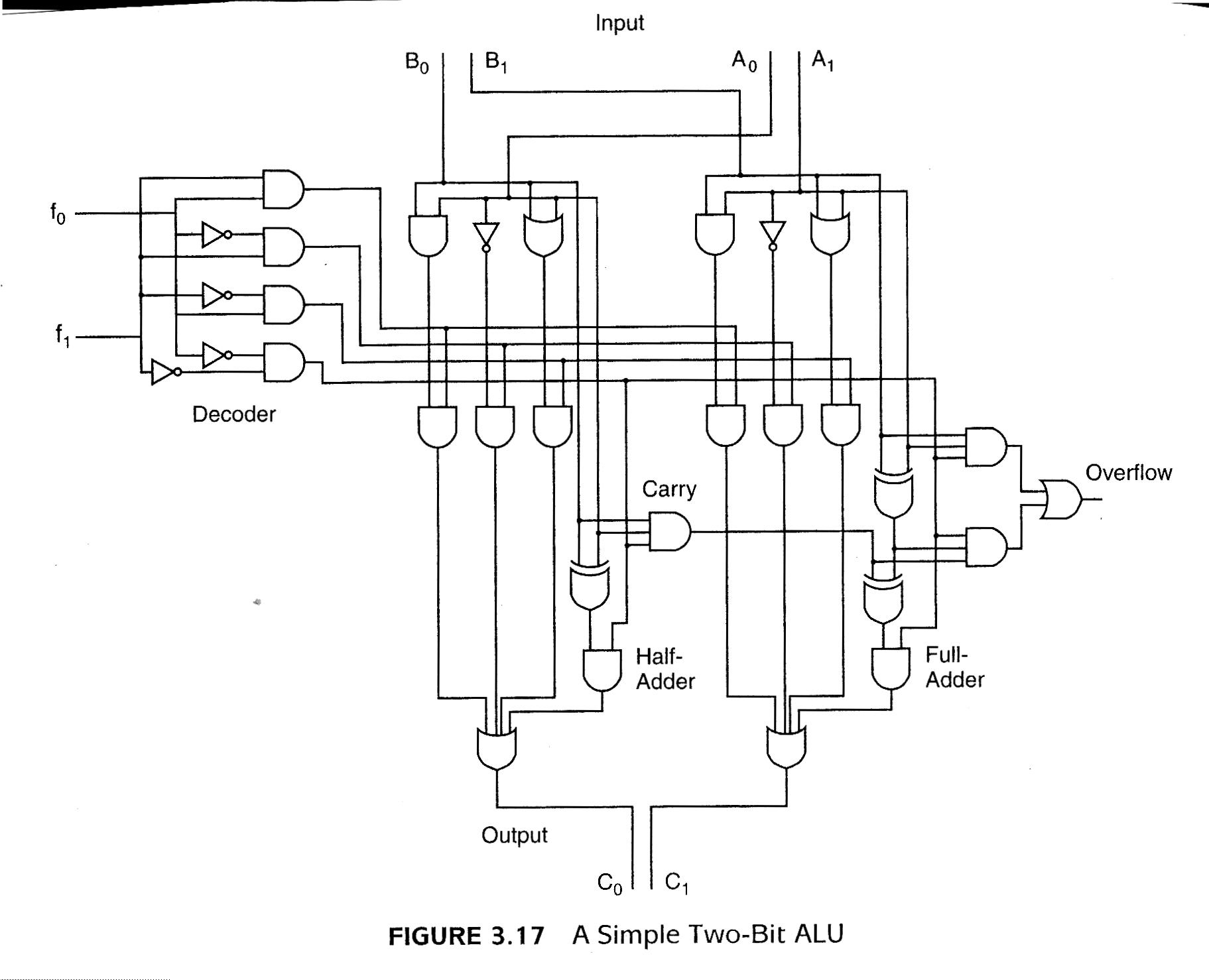
Figure 3.17 A Simple 2-bit ALU
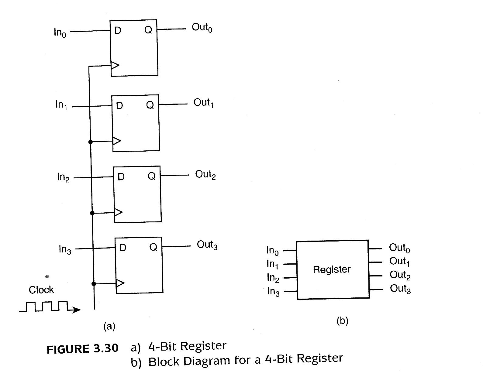
Figure 3.30 A 4-bit register
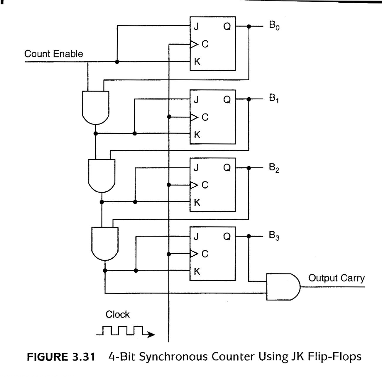
Figure 3.31 4-bit Synchronous Counter
Figure 3.32 4 x 3 Memory
Chapter 4: MARIE
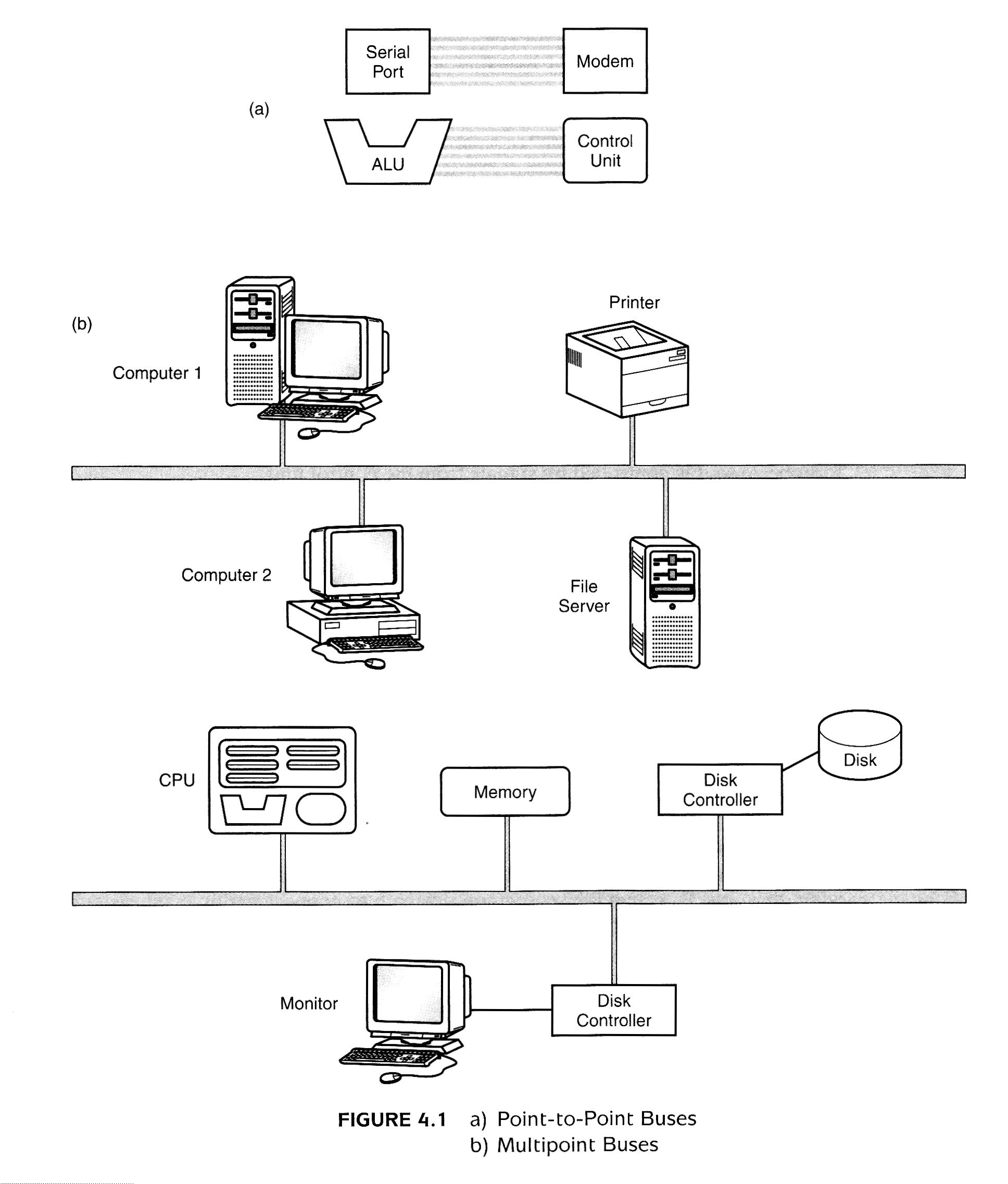
Figure 4.1 Buses
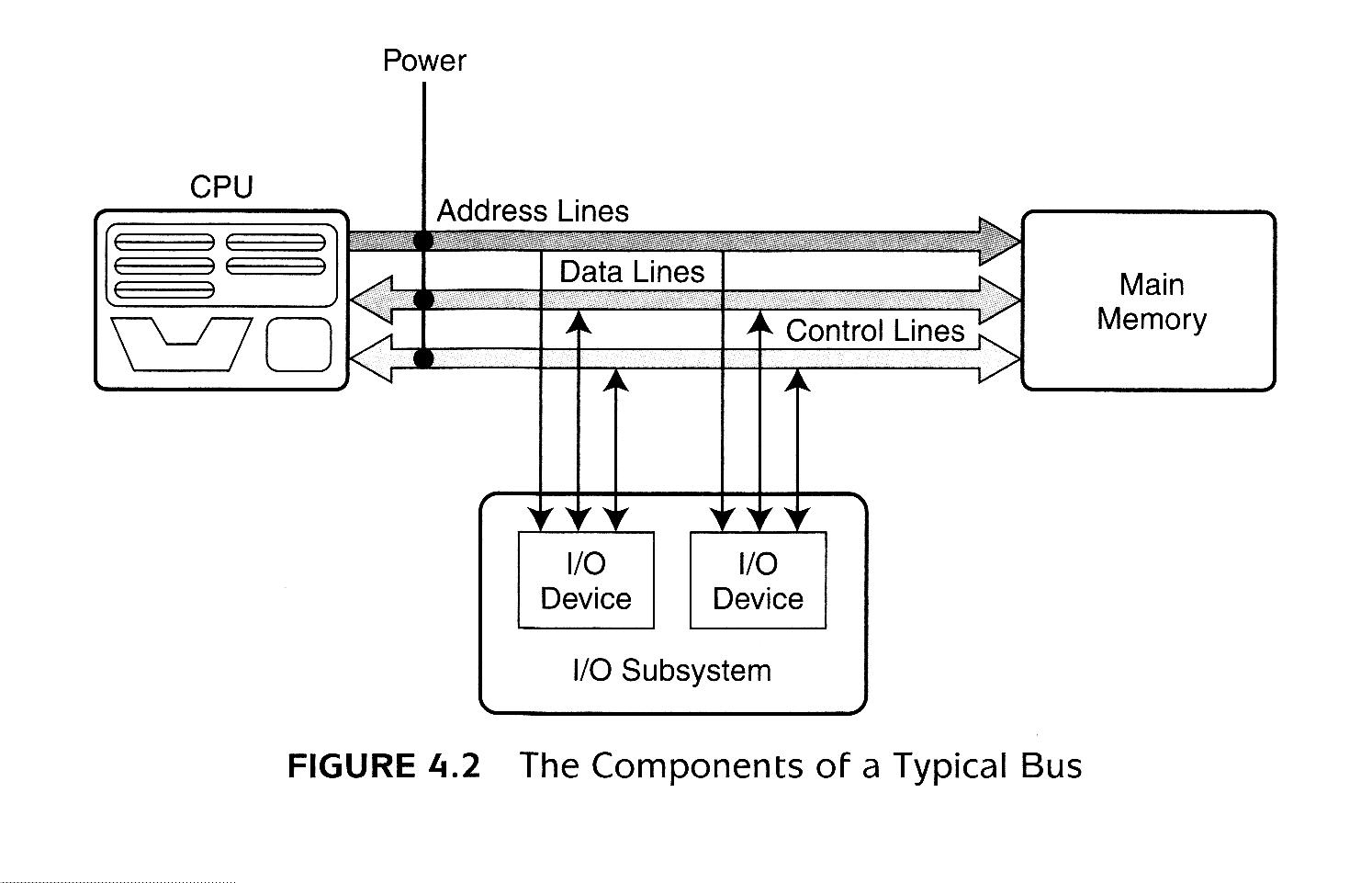
Figure 4.2 Components of a Typical Bus
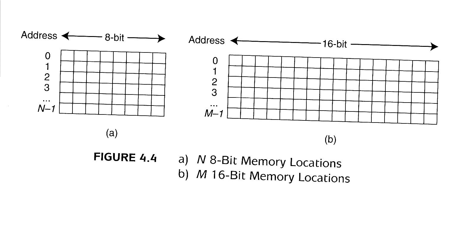
Figure 4.4 Memory
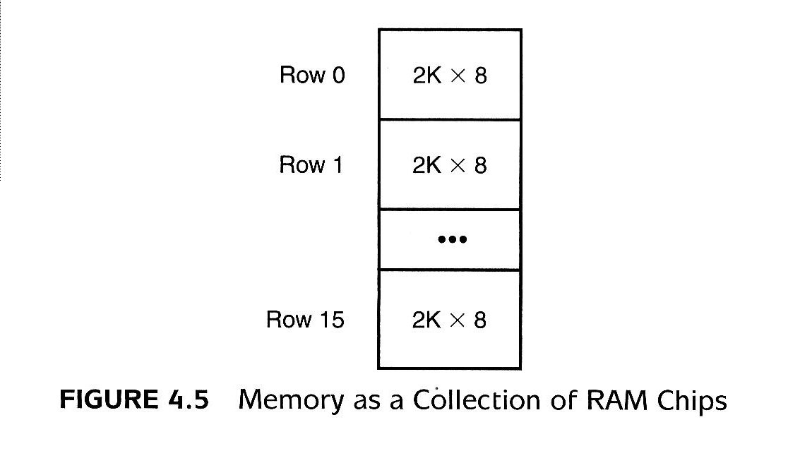
Figure 4.5 Memory as a Collection of RAM Chips
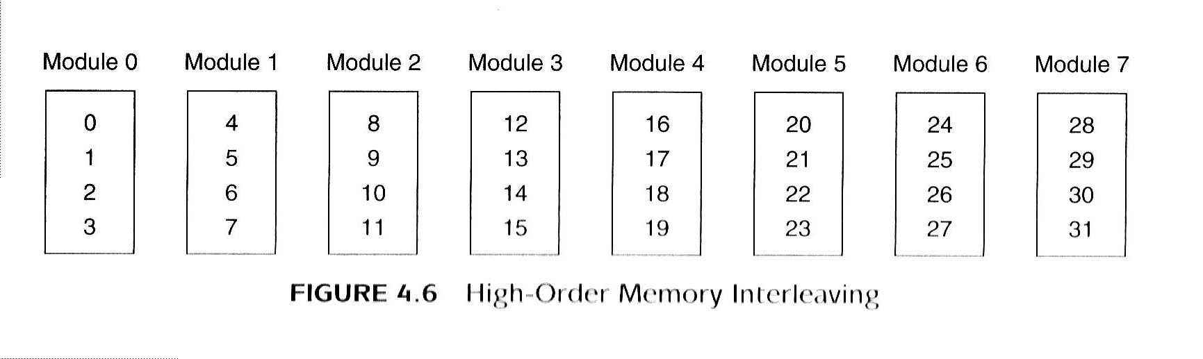
Figure 4.6 High-Order Memory Interleaving
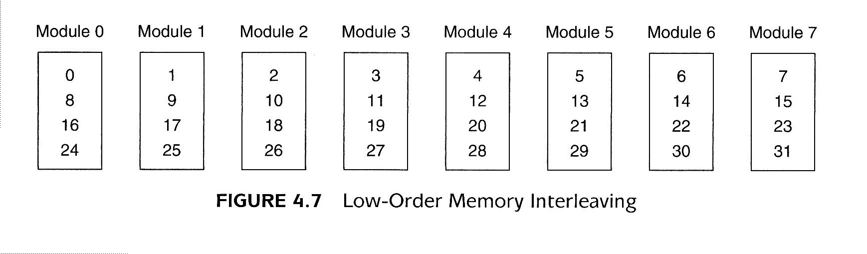
Figure 4.7 Low-Order Memory Interleaving
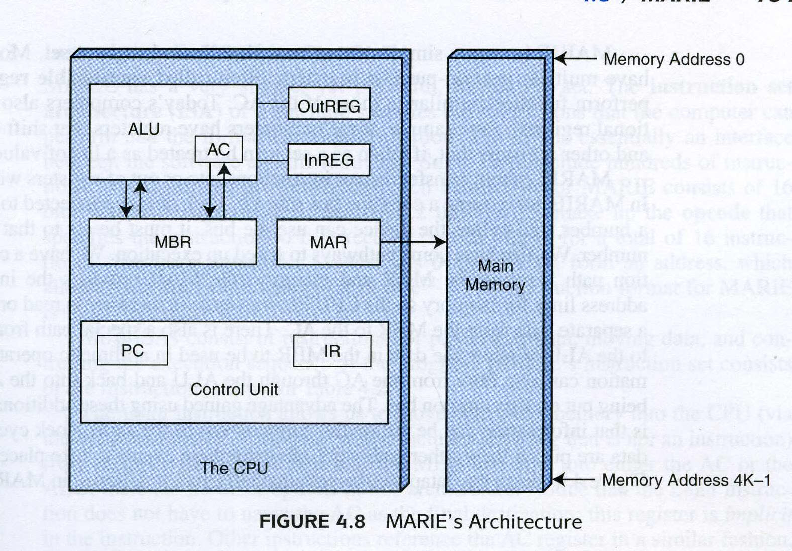
Figure 4.8 MARIE's architecture
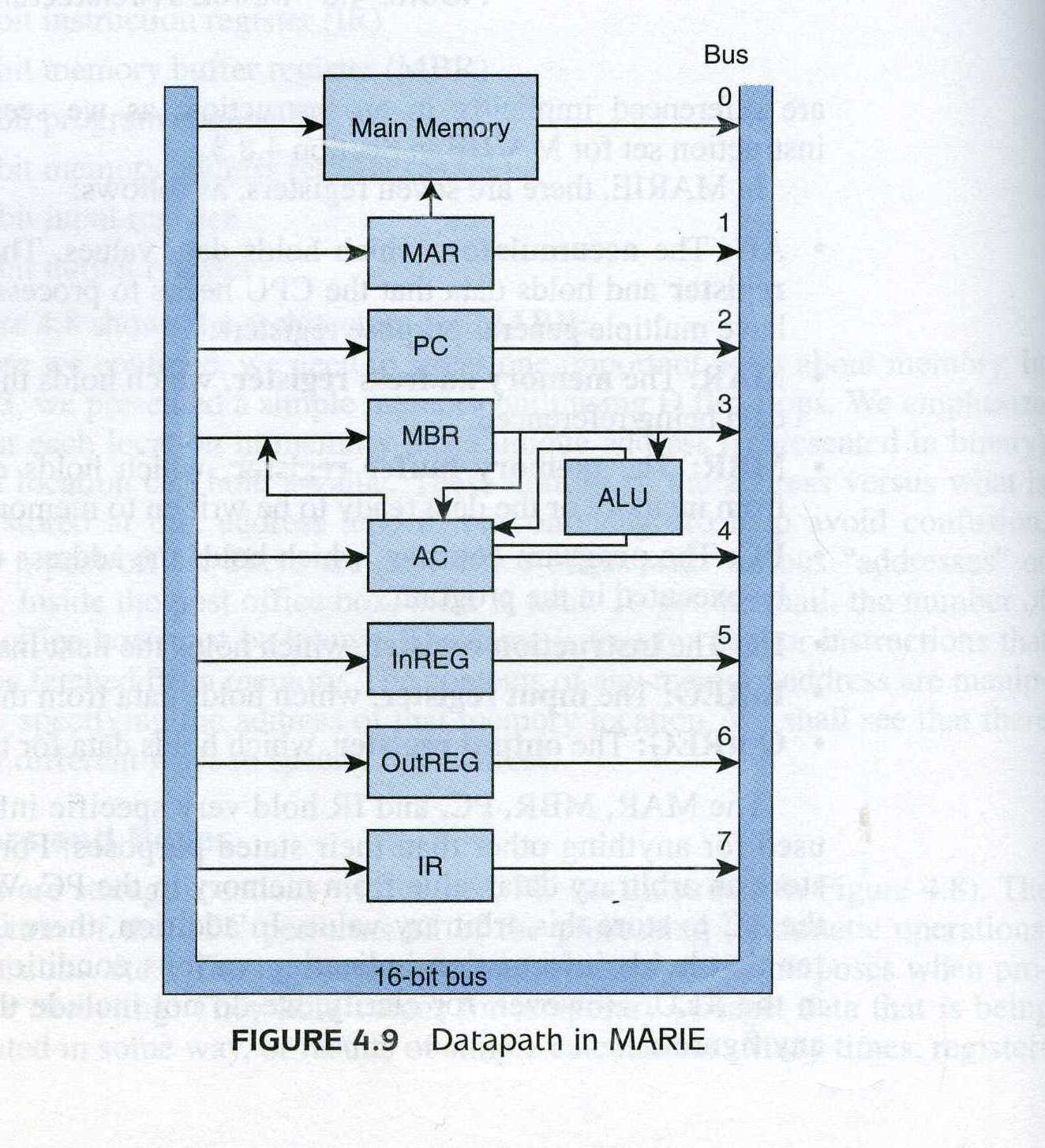
Figure 4.9 Datapath in MARIE
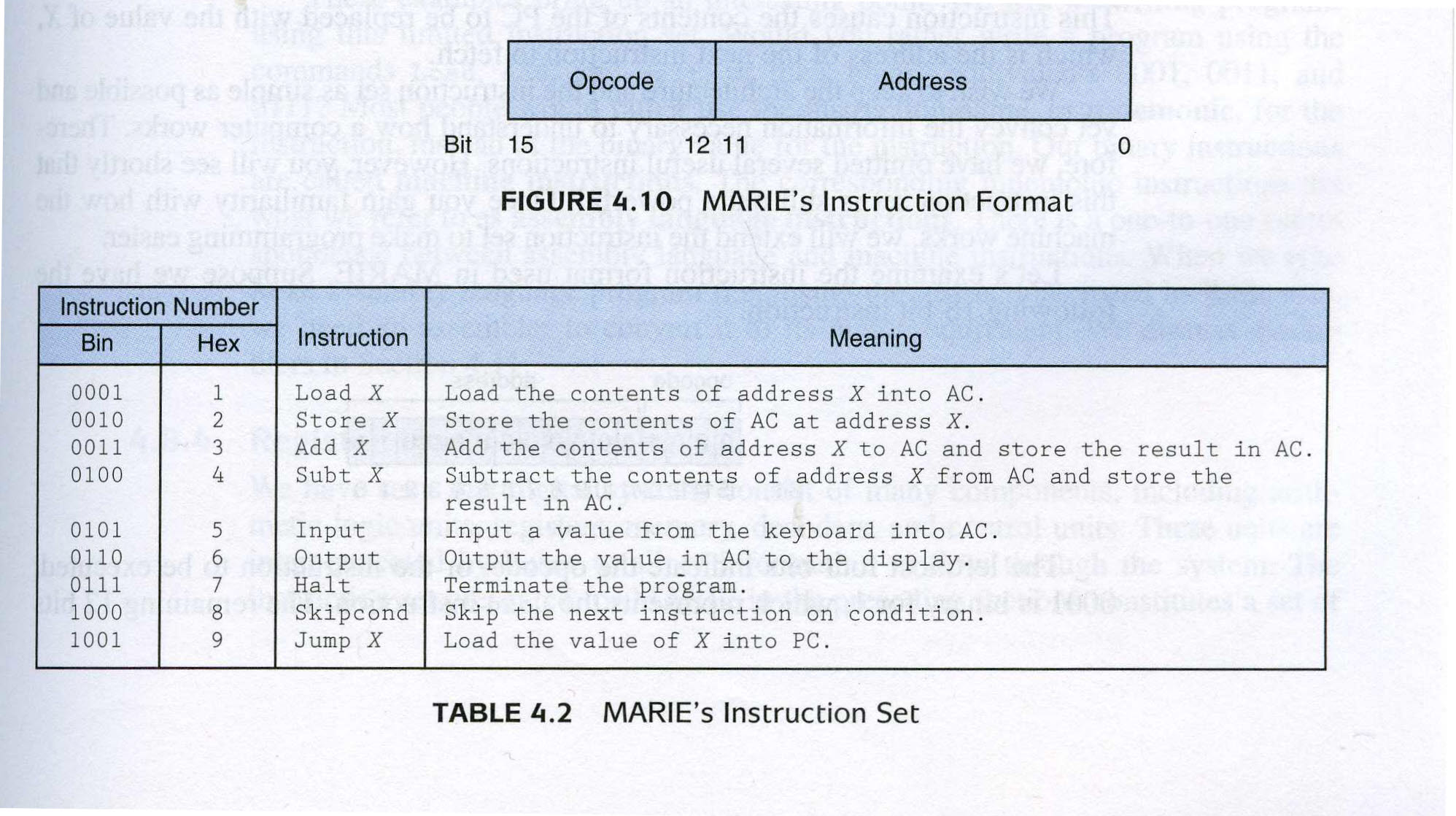
Figure 4.10 and Table 4.2
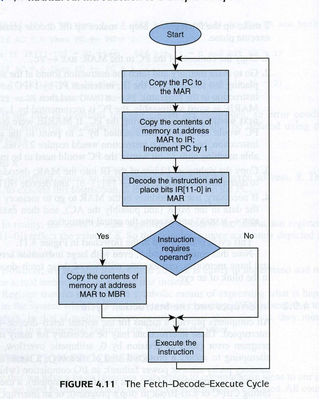
Figure 4.11 The Fetch-Decode-Execute Cycle
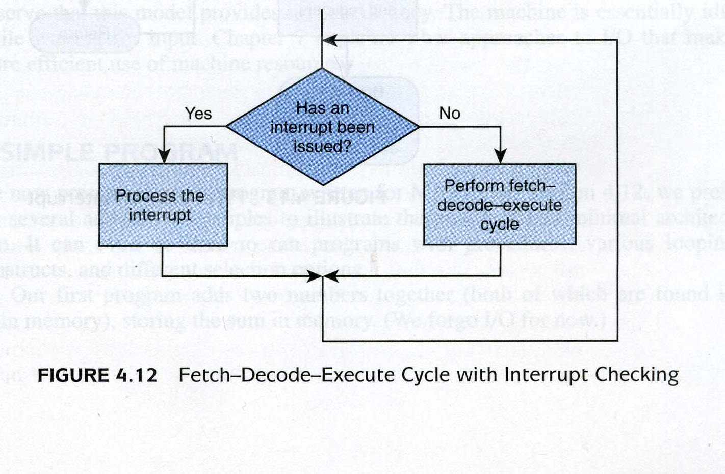
Figure 4.12 The Fetch-Decode-Execute Cycle with Interrupt Checking
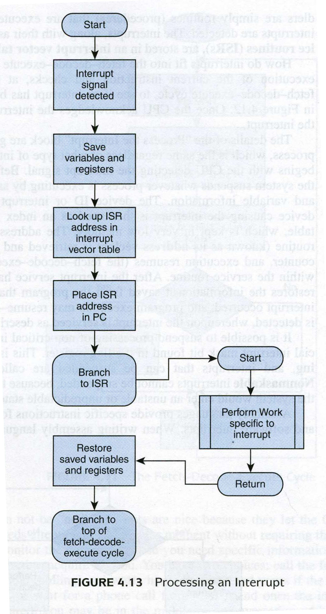
Figure 4.13 Processing an Interrupt
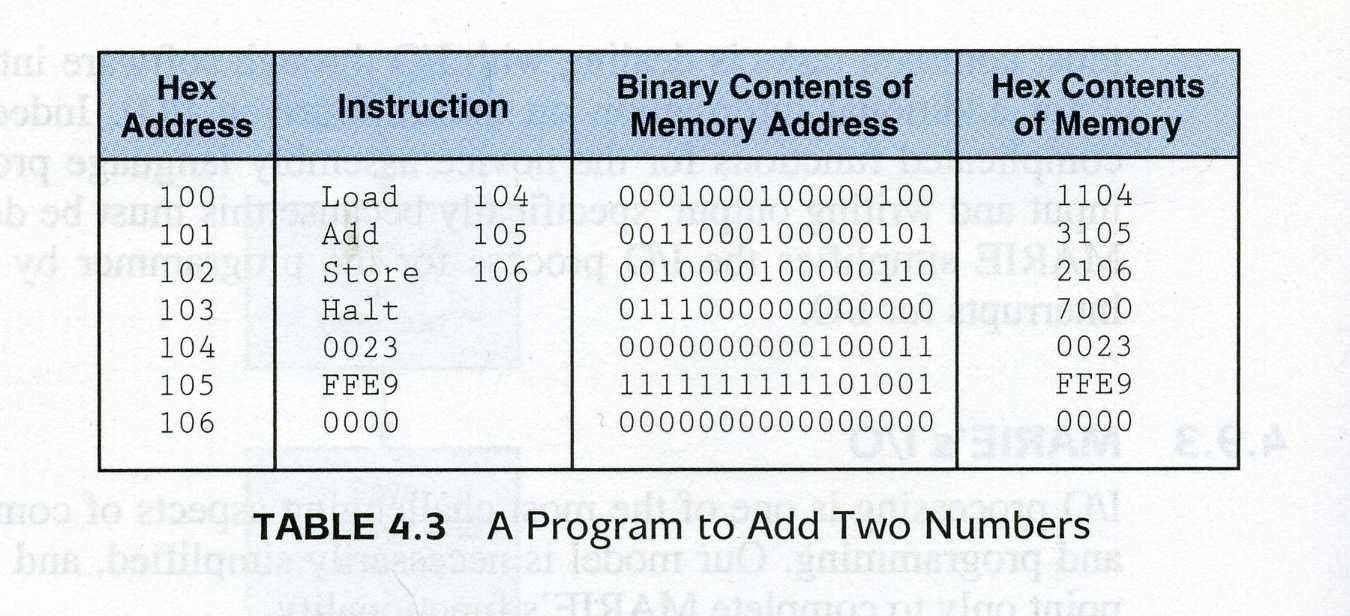
Table 4.3 A Program to Add Two Numbers
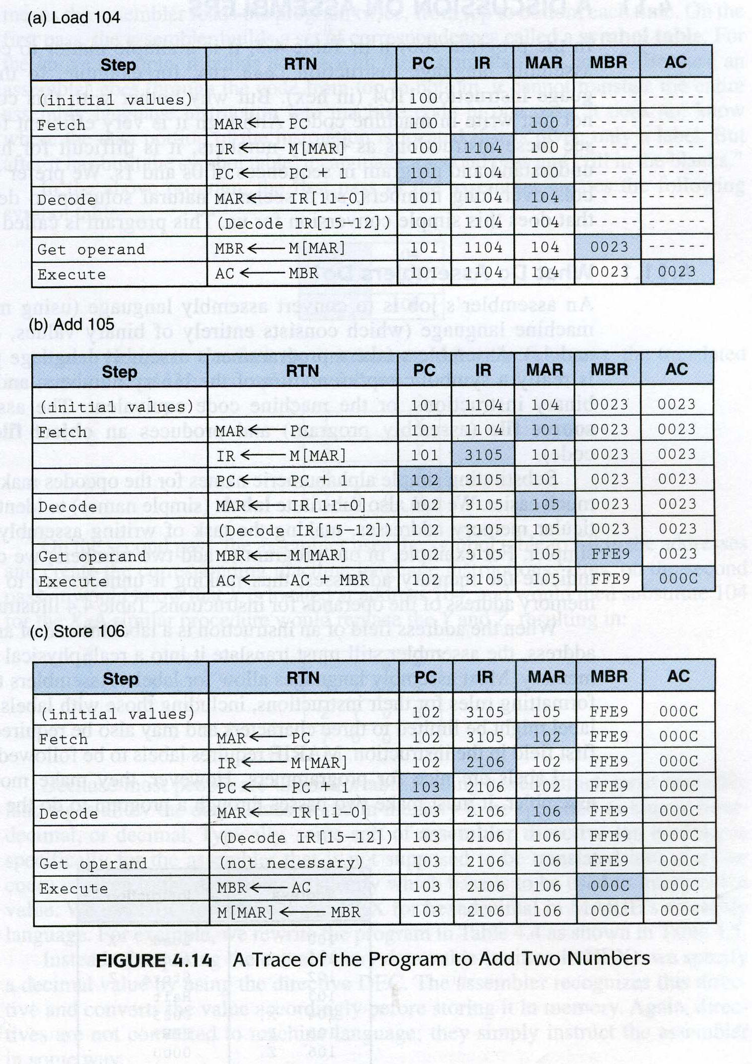
Figure 4.14 A Trace of the Program to Add Two Numbers
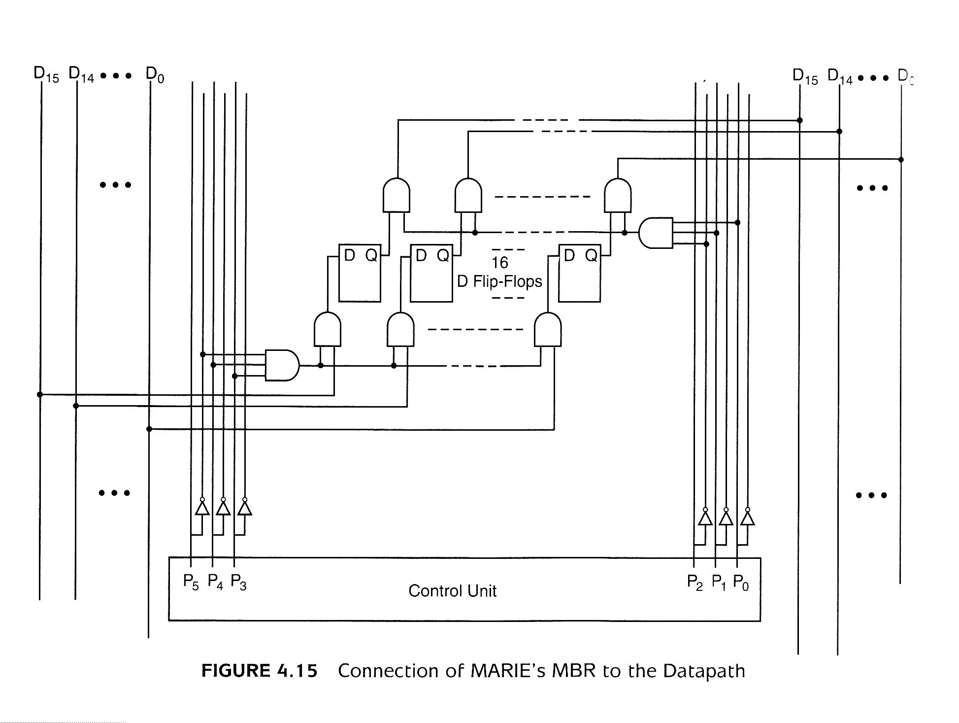
Figure 4.15 Connection of MARIE's MBR to the Datapath
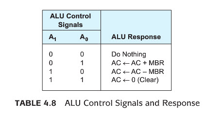
Table 4.8 ALU Signals
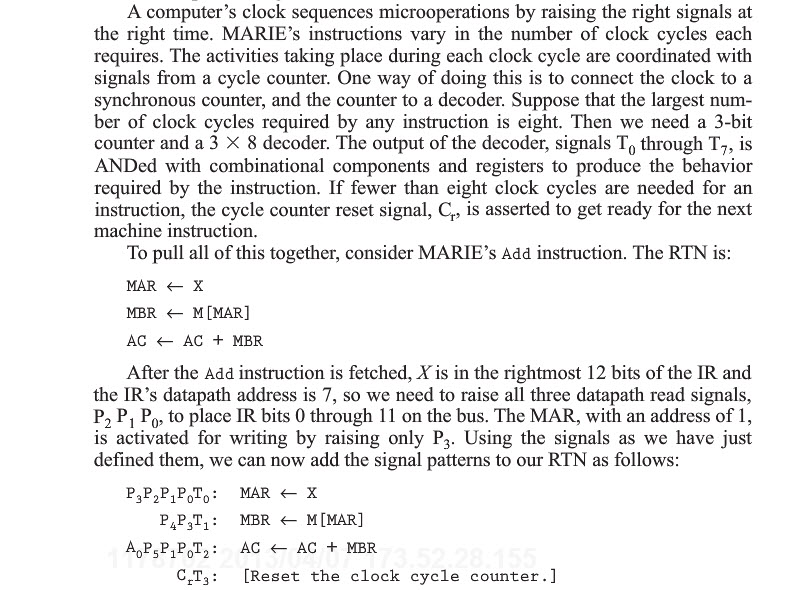
CU-generated signals for Add
Figure 4.16 Timing Diagram for the Microoperations of MARIE's Add Instruction
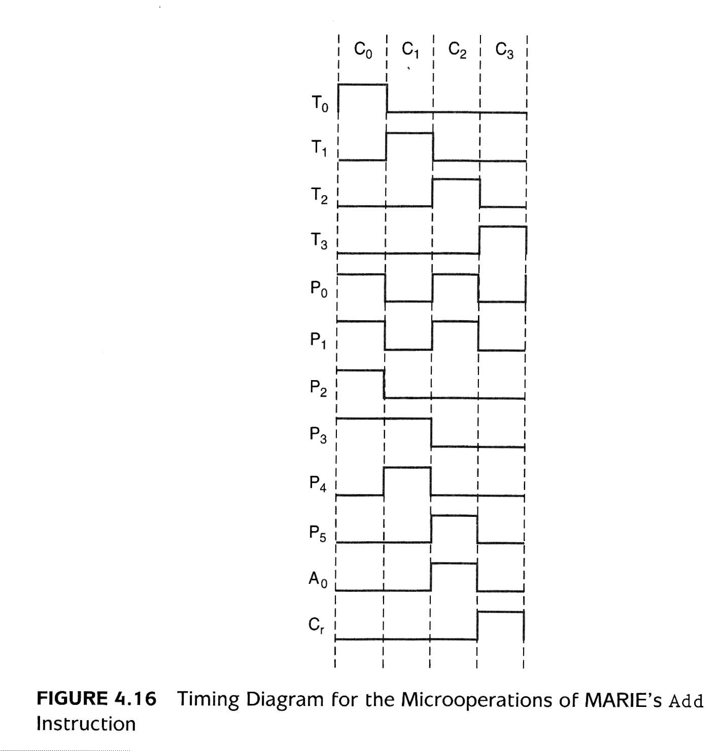
Figure 4.17 Hardwired Control Unit
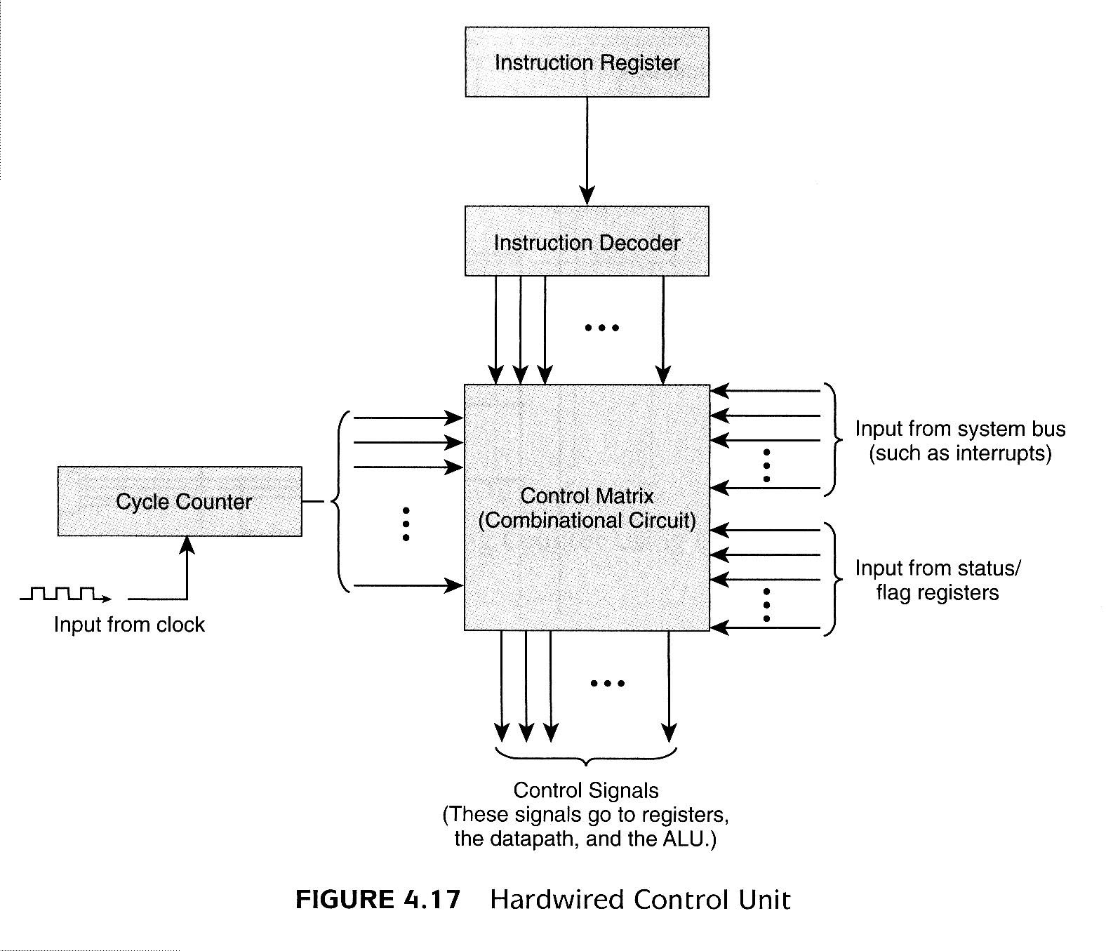
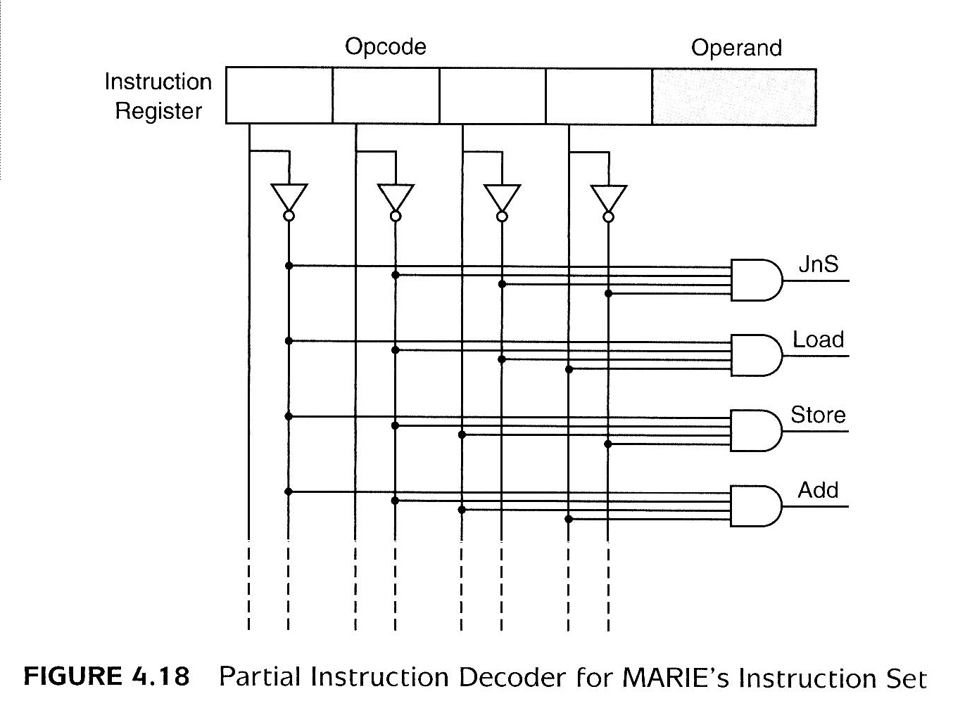
Figure 4.18 Partial Instruction Decoder for MARIE's Instruction Set
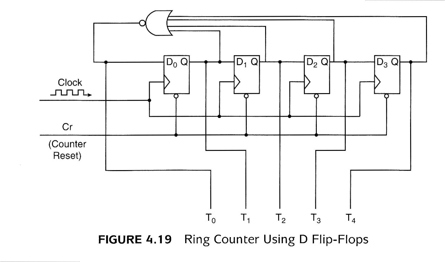
Figure 4.19 Ring Counter Using D Flip-Flops
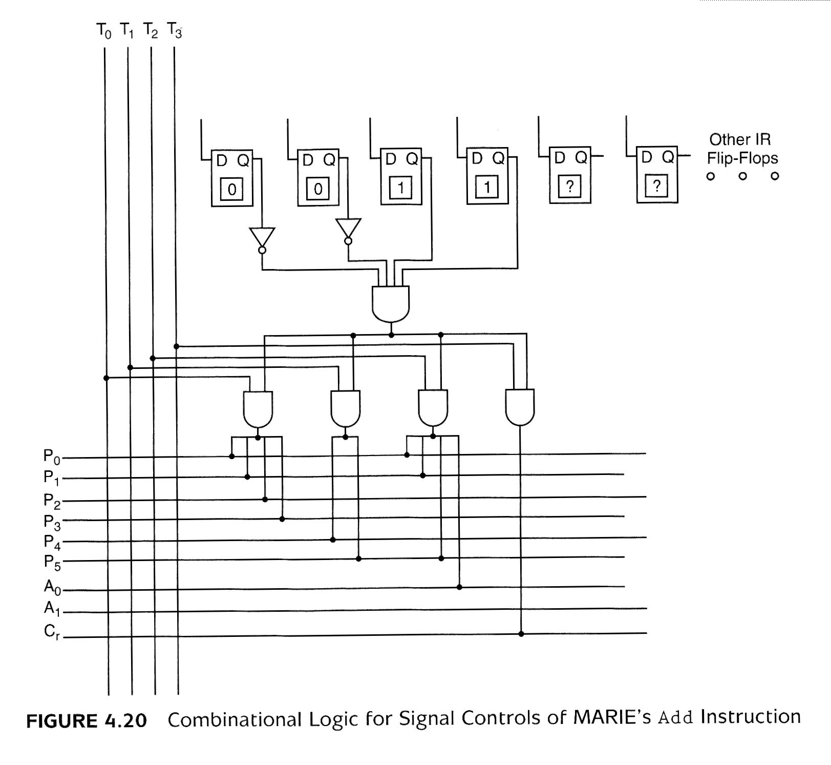
Figure 4.20 Combinational Logic for Signal Controls of MARIE's Add Instruction
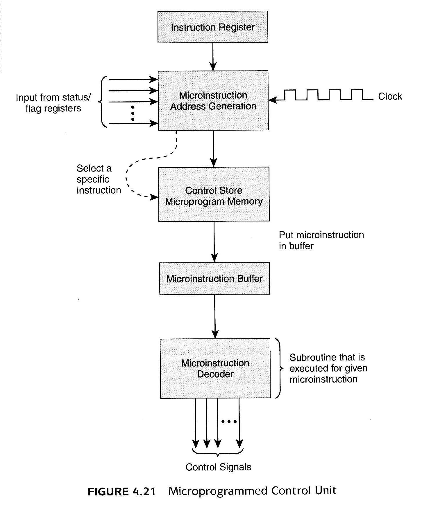
Figure 4.21 Microprogrammed Control Unit
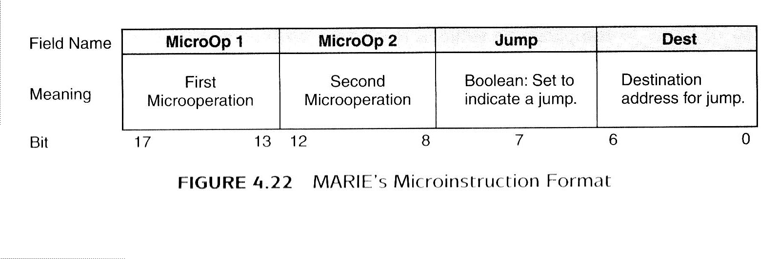
Figure 4.22 MARIE's Microinstruction Format
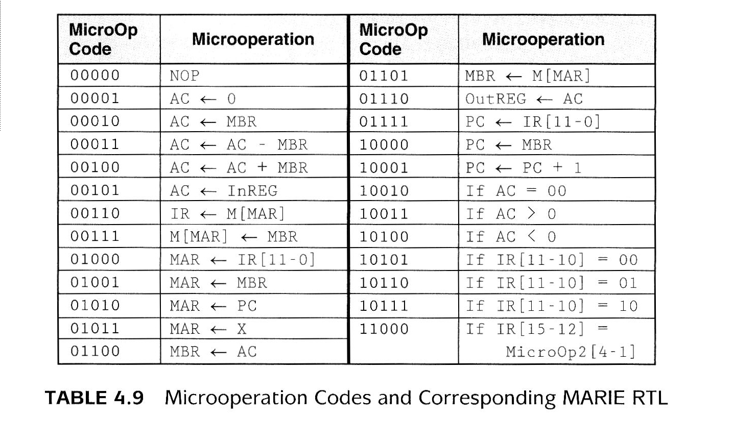
Table 4.9 Microoperation Codes and Corresponding MARIE RTL
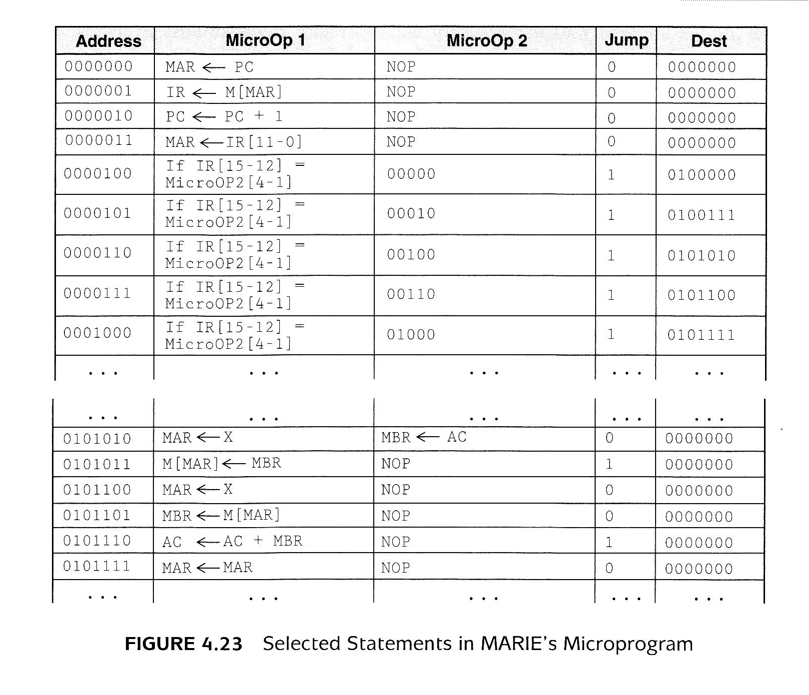
Figure 4.23 Selected Statements in MARIE's Microprogram
Chapter 7: I/O Figures
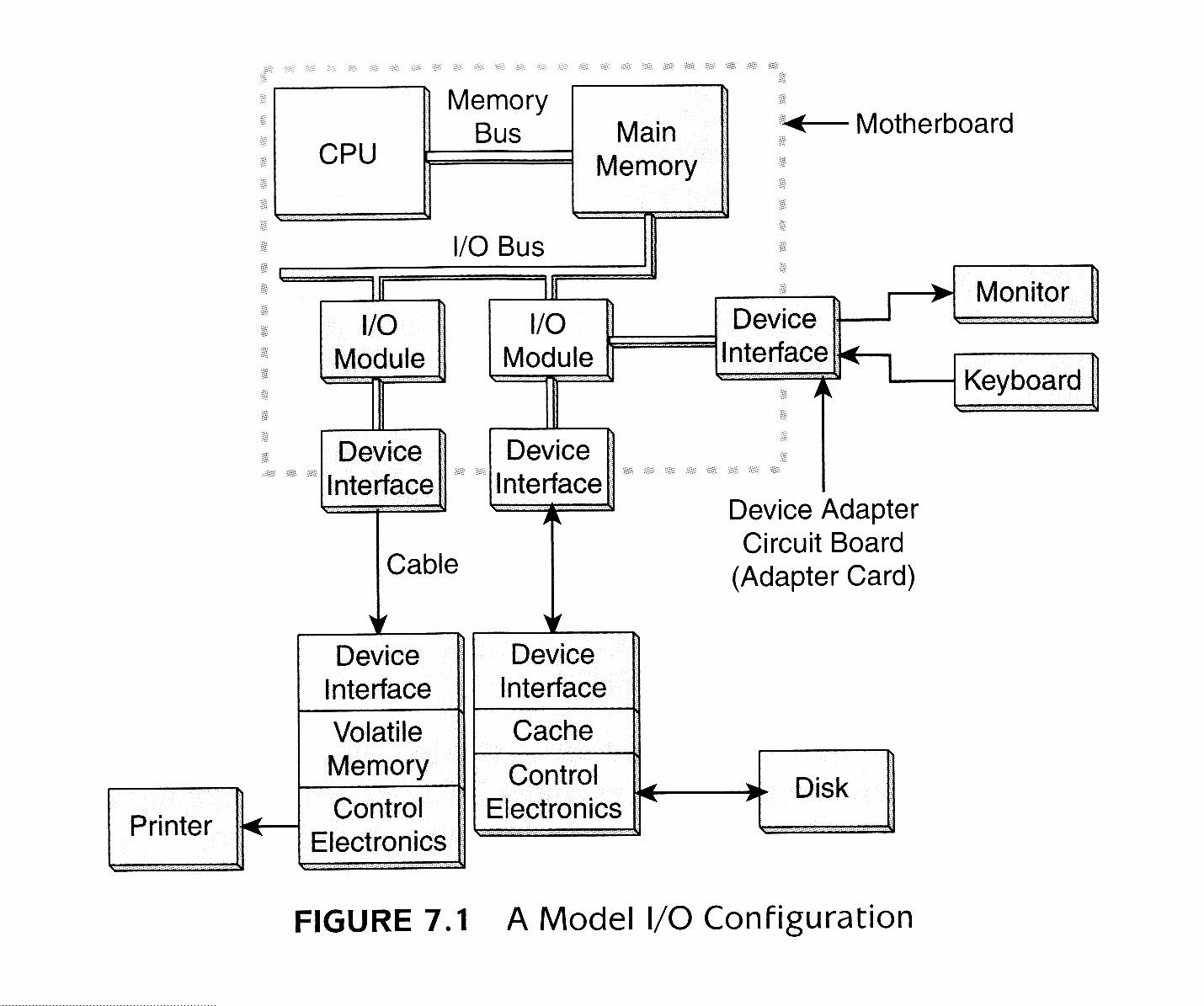
Figure 7-1 A Model I/O Configuration
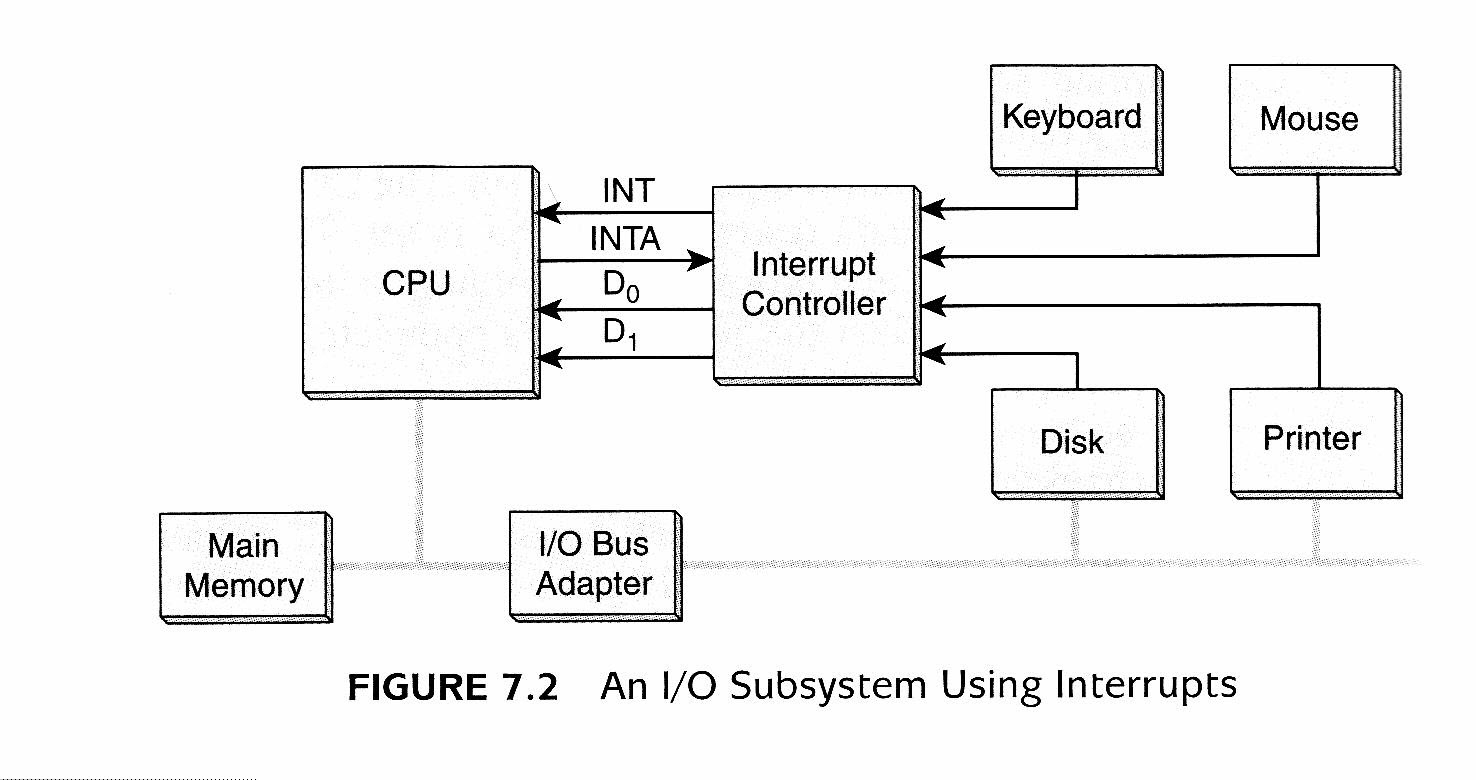
Figure 7-2 An I/O Subsystem Using Interrupts
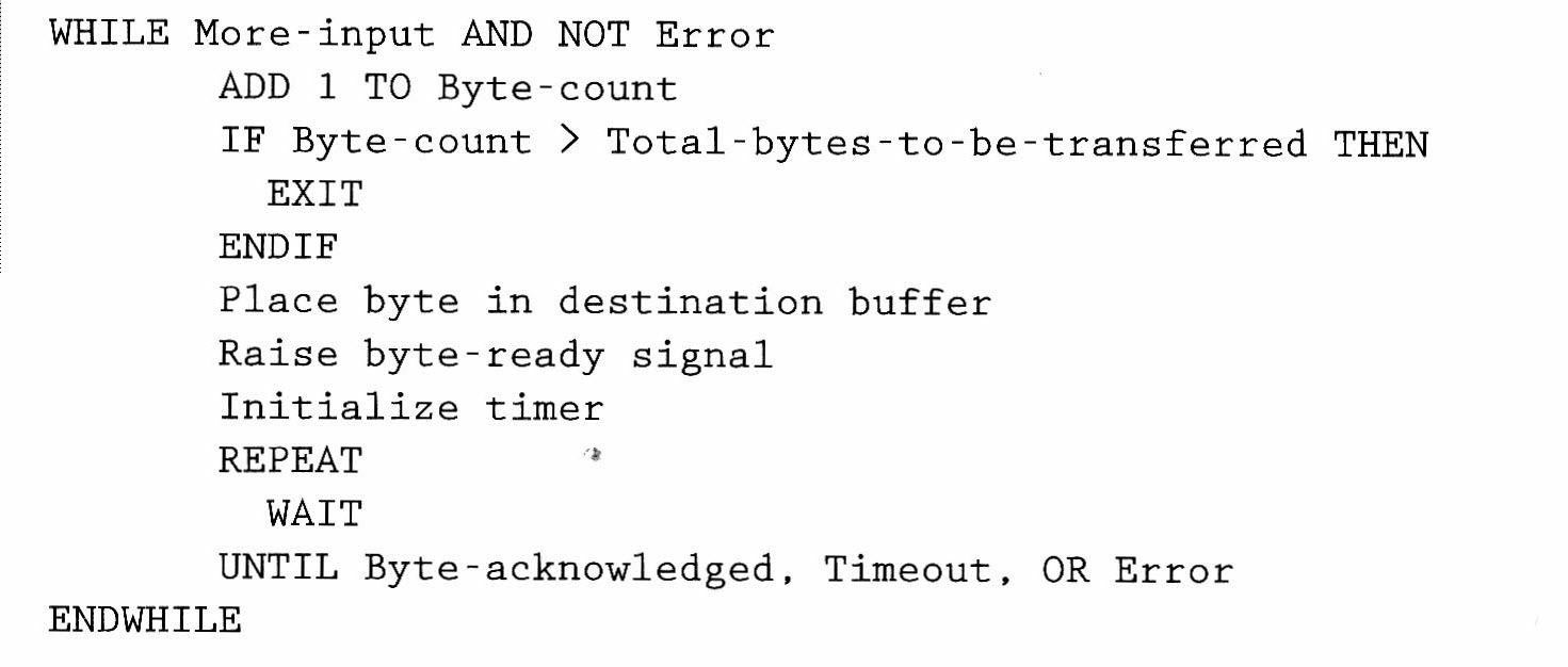
PIO and Int pseudocode
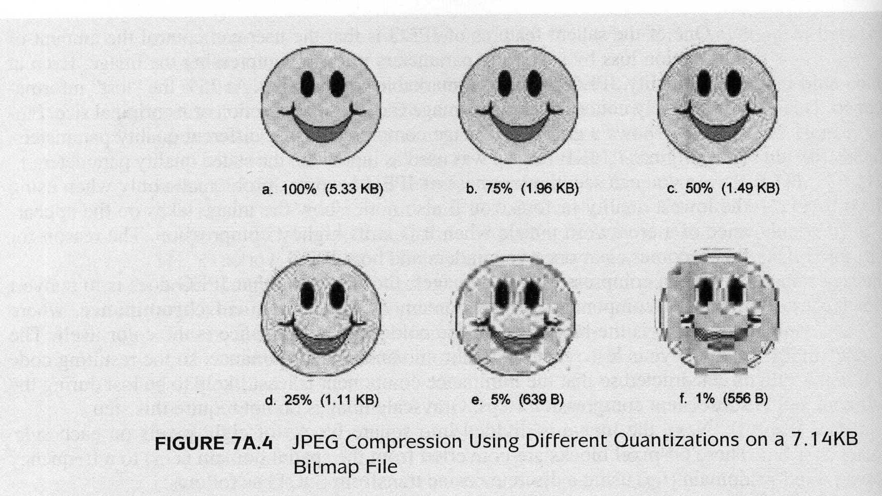
Figure 7A.4 JPEG compression
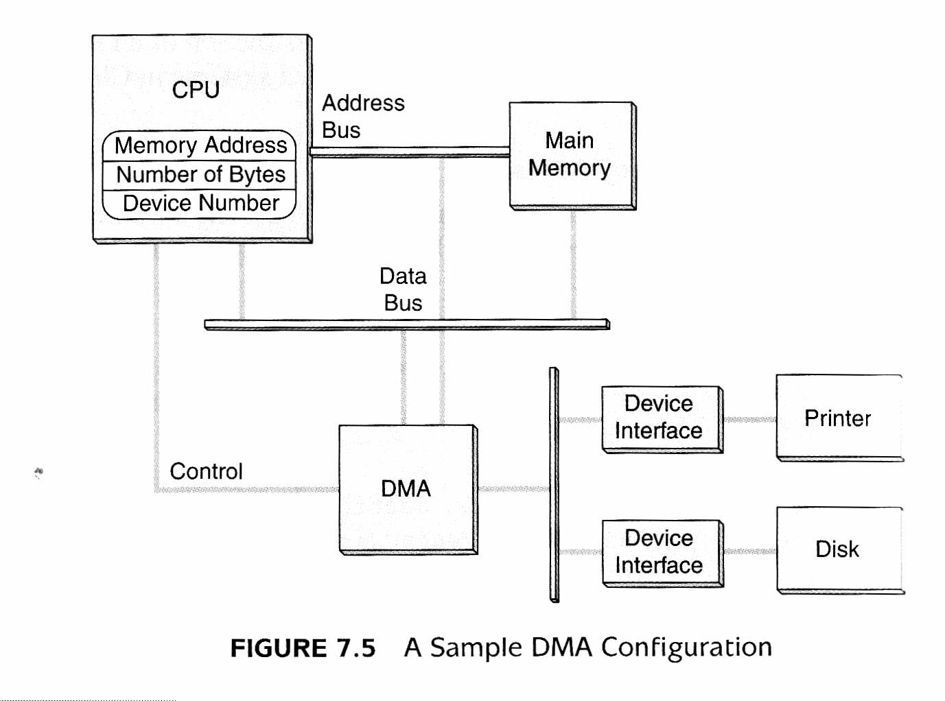
Figure 7-5 A Sample DMA Configuration
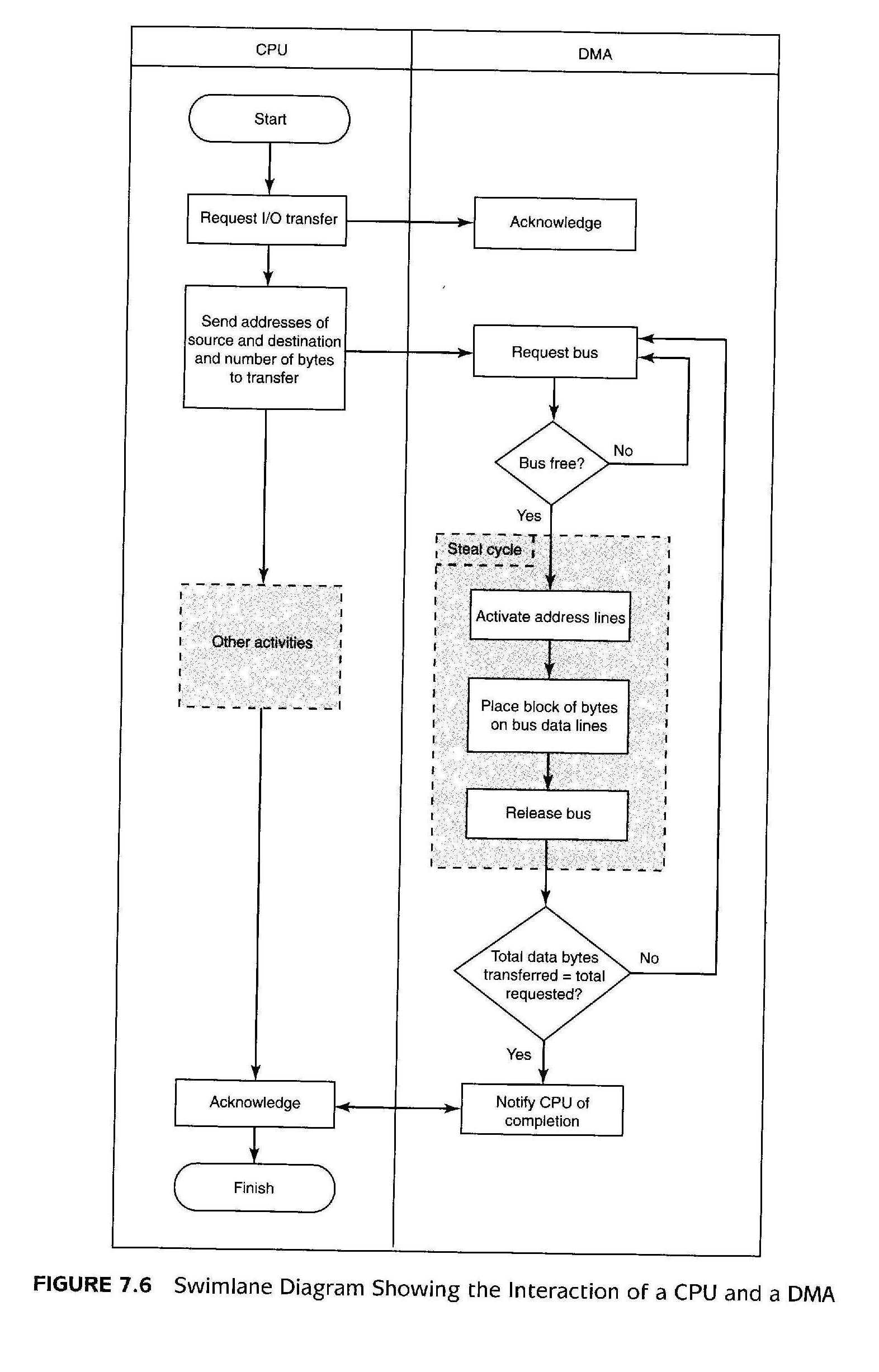
Figure 7-6 A Channel I/O Configuration
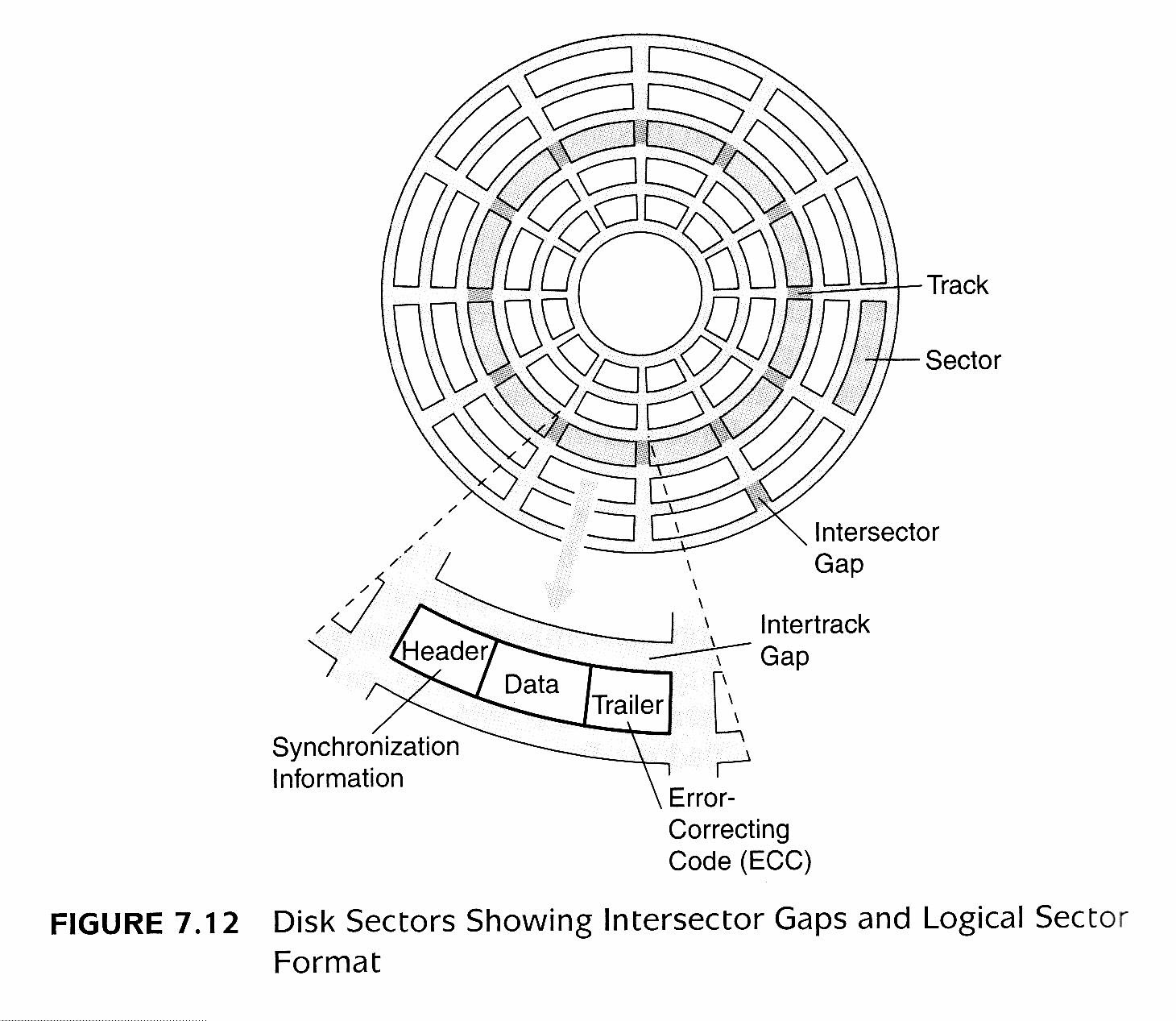
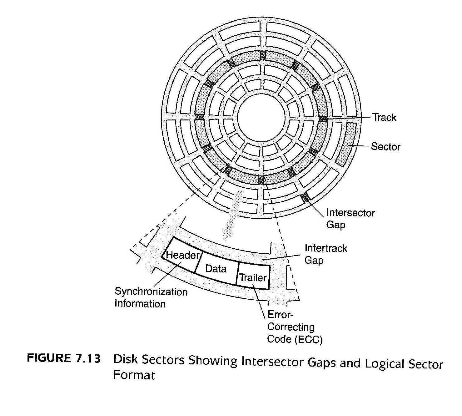
Figure 7-12 Disk Sectors Showing Intersector Gaps and Logical Sector Format
Figure 7-13 Rigid Disk Actuator (with Read/Write Heads) and Disk Platters
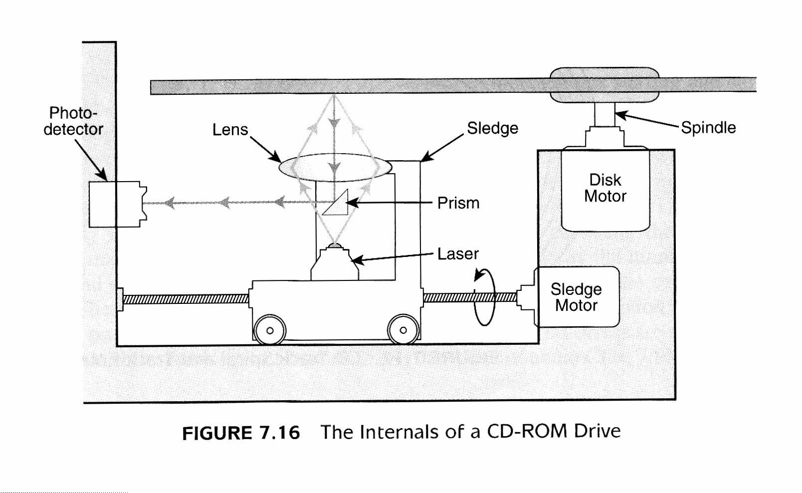
Figure 7-16 The Internals of a CD-ROM Drive
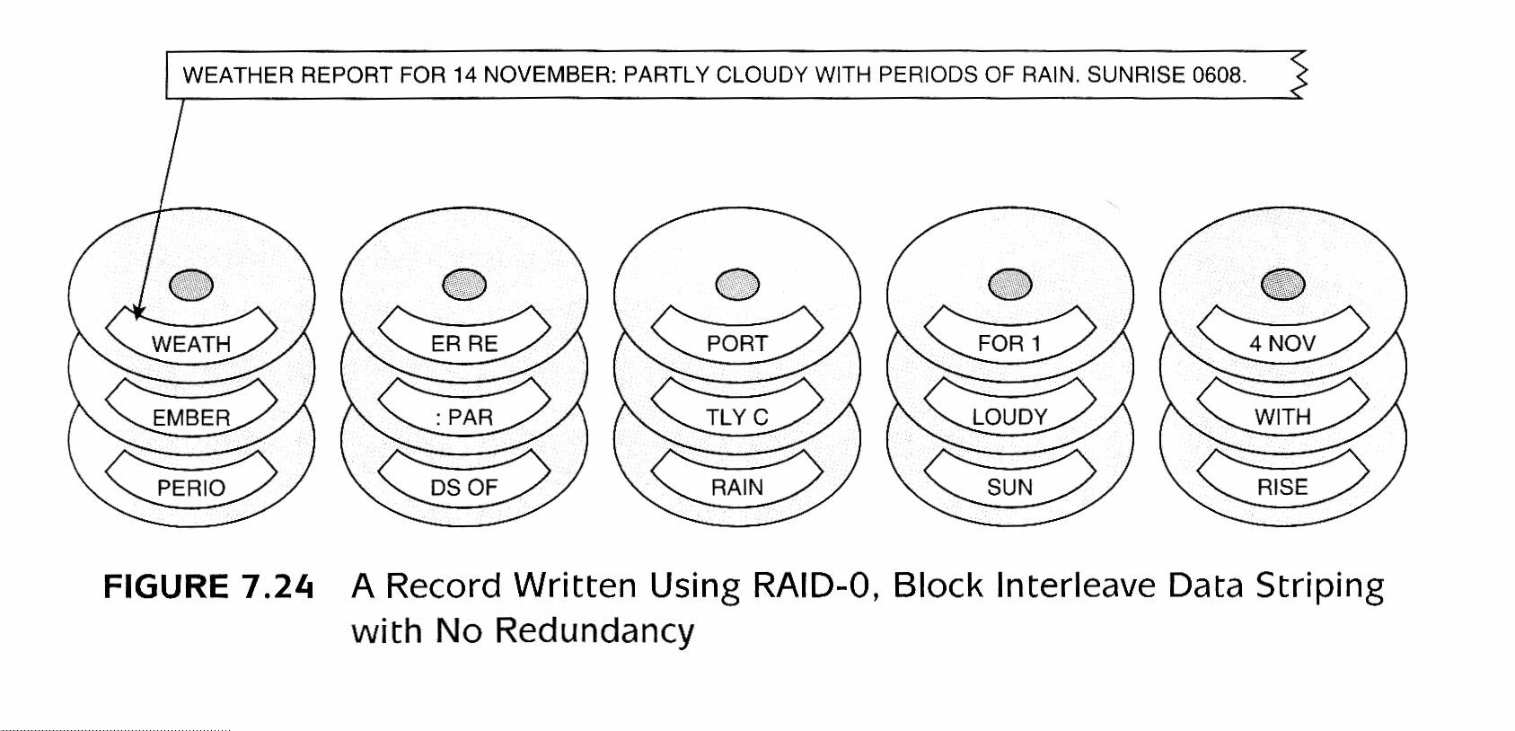
Figure 7-24 RAID-0, Block Interleave Data Striping with No Redundancy
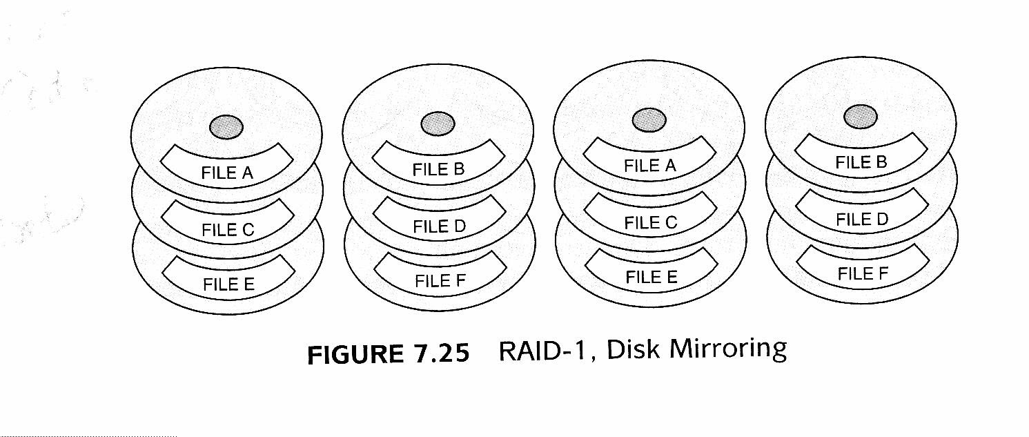
Figure 7-25 RAID-1, Disk Mirroring
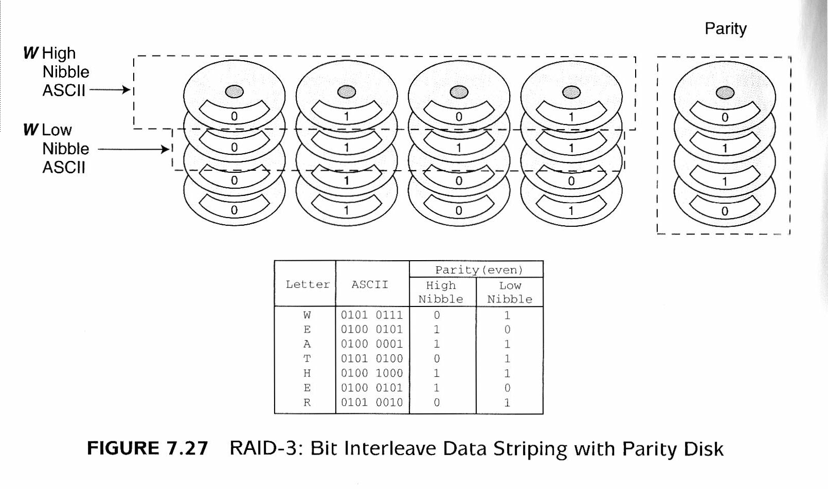
Figure 7-27 RAID-3: Bit Interleave Data Striping with Parity Disk