CIS 41
Computer Graphics
Chapter 1
Pixels
Digital vs Film Photography
- Like digital cameras, film ranges in resolution (expressed in line per inch)
- Film resolutions exressed in megapixels range from 3 (for low-end consumer negative film) to 25 (for high-end pro film)
- Film is analog (both the resolution and color level) and thus continuous; digital is ... well, digital.
Rasters
- 'Array' (in the sense of sequence, not data structure) of pixels
Frame Buffer
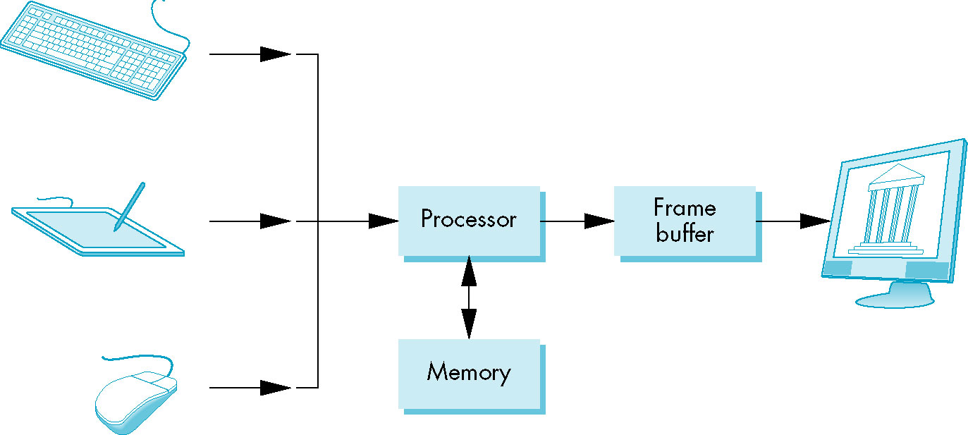
- Memory containg the pixels for the graphics image
- Core element of the graphics system
- depth, precision - # bits per pixel
- full-color, true-color, RGB-color -
- RGB based color specs
- usually 24 bits (8 bits ... 0-255/red, green. blue) or more (floating point value for red, green, blue)
- true-color vs pallete-based (color look-up table) color systems
- At minimum the frame buffer holds the color (color buffers) information about the pixels
Rasterization
- Process of converting geometric entities (lines, polygons, images) into specific pixel locations and values
in the frame buffer
- Also known as scan conversion
CPU vs GPU
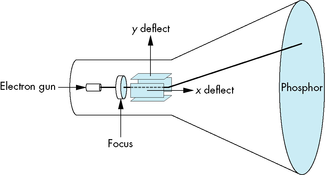
Output Devices
- vector vs raster
- refresh rate
- interlaced vs noninterlaced (progressive)
- aspect ratio
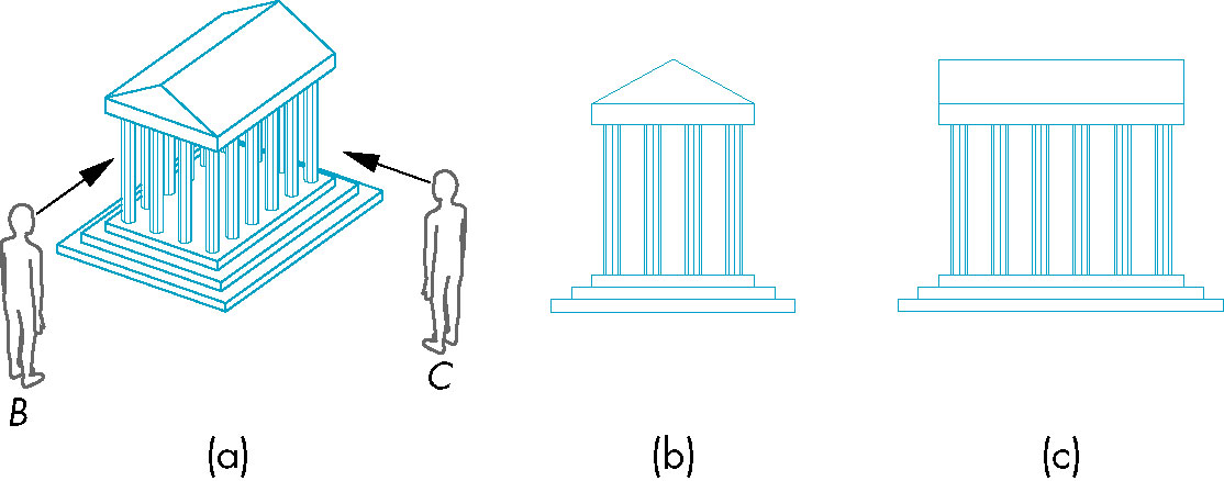
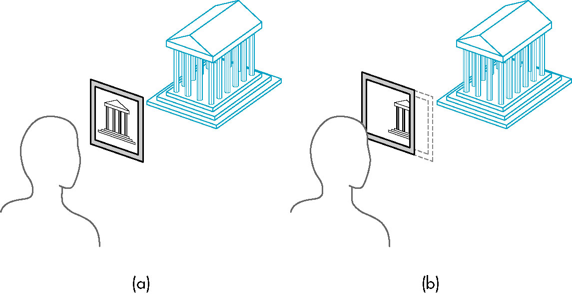
Images
- Objects - usually specified by vertices
- Viewers - form images of objects
- Image is not the same thing as the object
- In particular the image of a 3D object is a 2D projection on the film plane, or our retina
- Light sources
- Point source emits light from a single point in equal intensity in all directions
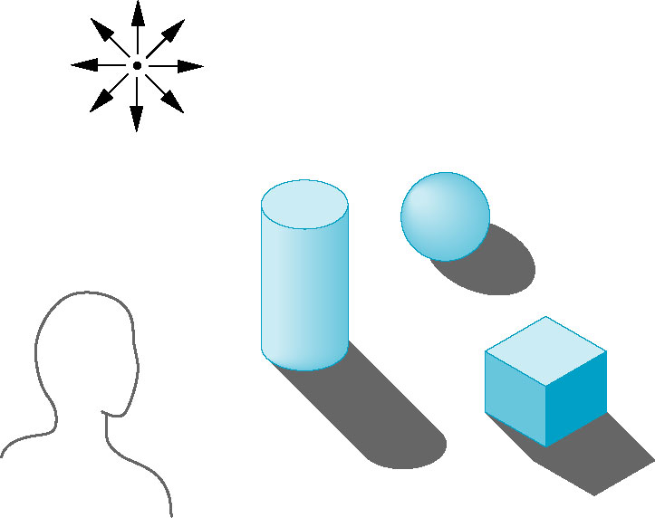
- Rendering - The process of generating an image from a model (description) of an object.
Image Formation
- ray directed line extending to infinity in one direction (from its source)
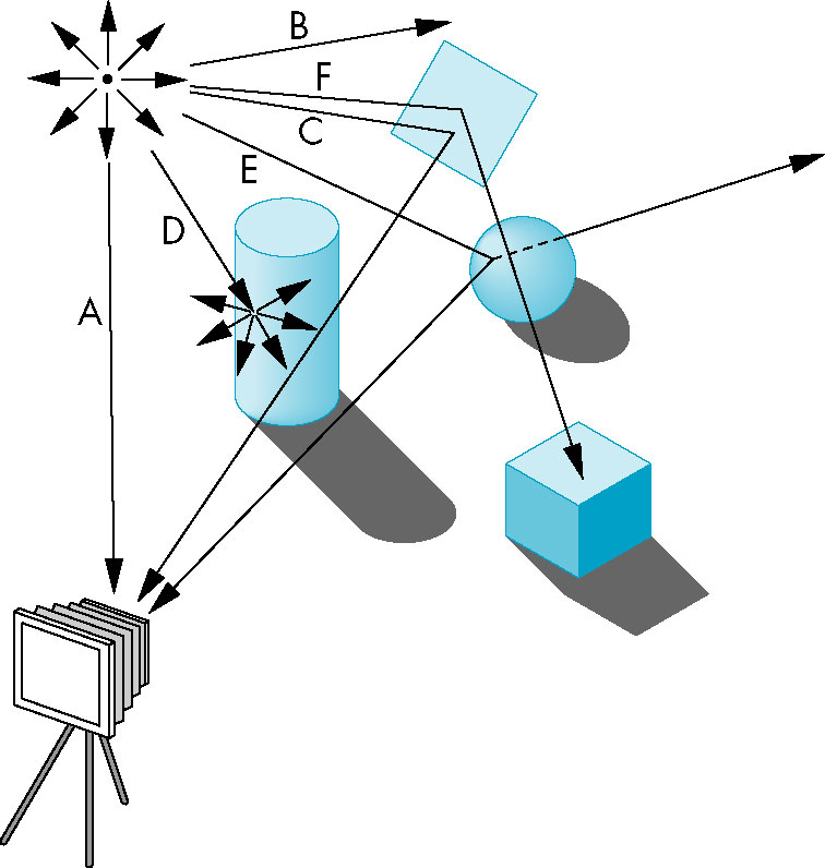
Ray Tracing/Photon Mapping
- Rays are traced from light source or camera and their intersection and interaction with an object is computed.
- Since many rays go off to infinity, we often employ the reverse process known as ray casting
i.e., start at the viewer and extend the rays into the image
- Even that is computationally too expensive for real time rendering (though we're getting there)
Radiosity
- Takes into account light from sources other than the direct light source
- Reflection, indirect lighting play a role in the algorithm
- Provides a more realistic rendering
- Again, computationally too expensive for real time rendering
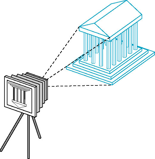
Imaging Systems
Physical Systems
Pinhole Camera
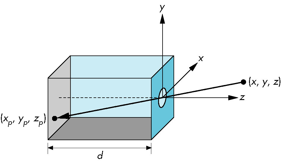
- Single ray of light from each point enters
- Projection of point onto film plane
- Field/angle of view
- Given camera with depth
d and height:
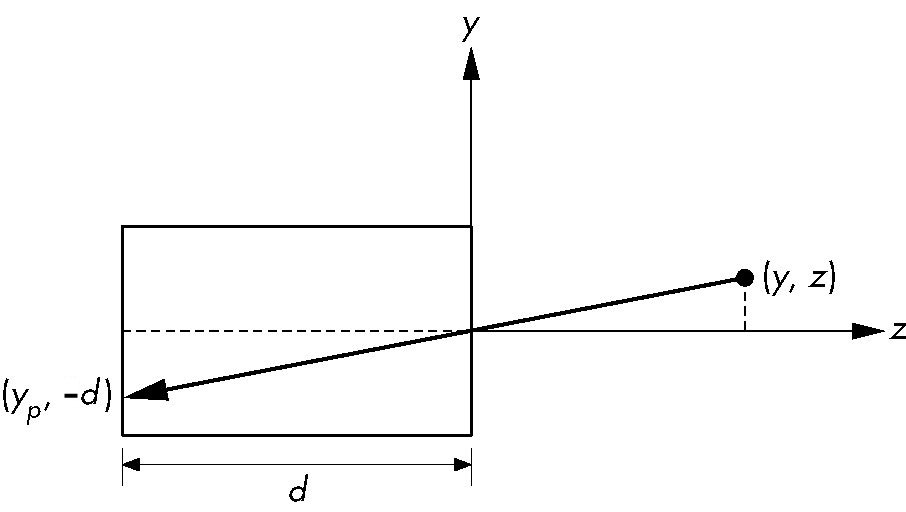
- Point
(x, y, z projects onto point (xp, yp, -d) where
yp = -(y * d) / z, and
xp = -(x * d) / z, and
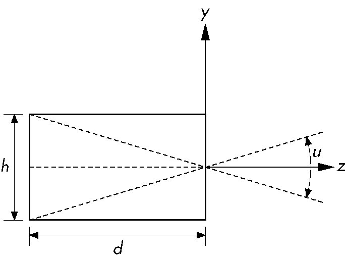
- Angle of view (θ) is 2 atan(h / (2d)) (tan θ/2 = h/2d → θ/2 = atan(h/2d) → θ = 2 atan(h/2d))
- Upside of pinhole camera: infinite depth of field-- whole image is in focus
- Downside of pinhole camera
- Very little light enters via pinhole
- Angle of view is fixed (constant function of height and depth)
Human Visual System
- Retina
- Rods and cones - receptors on retina
- Rods - used for low-light vision
- Color vision is due to interactions among three types of cones
- Resolution (visual acuity) based upon size of rods and cones on retina
- Measure of ability to distinguish between two adjacent points
- Brightness - perception if light intensity
- Three cones means we only need to work with three primary colors.
- Highly complex high-level intermediate processing between photoreceptors and brain
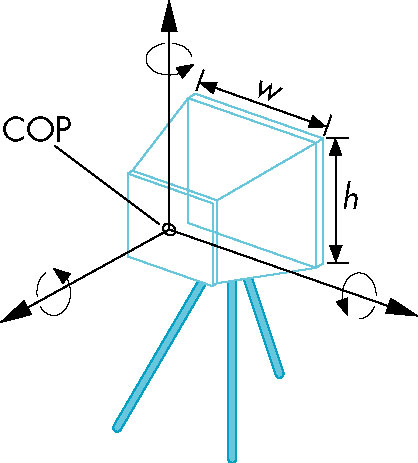
Synthetic Camera Model
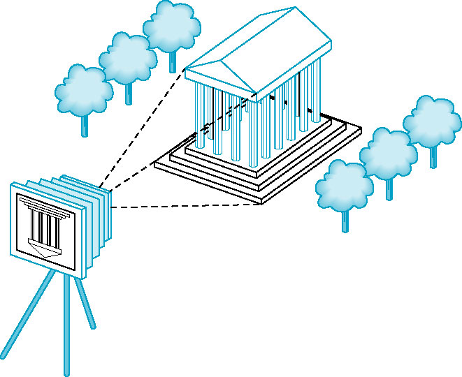
Basic principles:
- Object and viewer are completely independent
- All calculation can be done with simple geometry
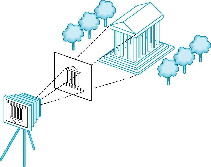
- Placing the projection plane (image plane) in front
of the camera lens keeps it right-side up (rather than flipped as would be the case were it
behind the camera).
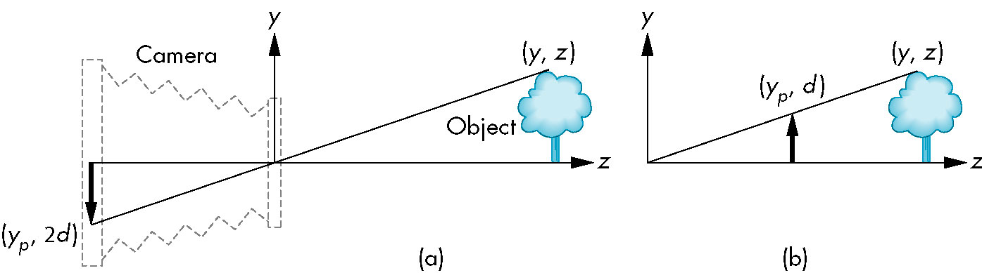
- Center of Projection (COP) - center of the lens
- Projector - line from a point on the object to the center of projection
- The image of the point is the point where it passes through the projection plane.
- Clipping window or rectangle defines field of view; points
outside that rectangle do not appear in the image.
Interfacing with a Graphics System/Library
- As a user
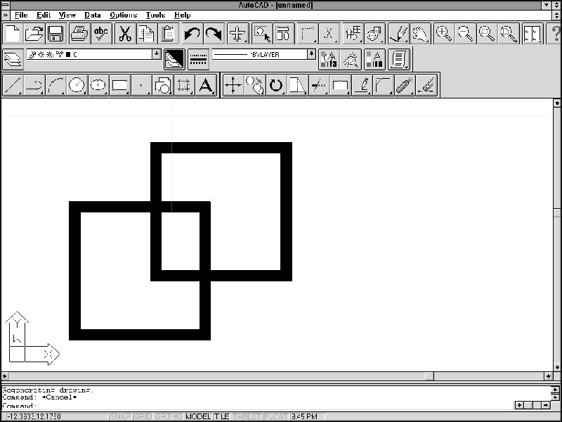
- As a programmer using an Application Programmers Interface (API)
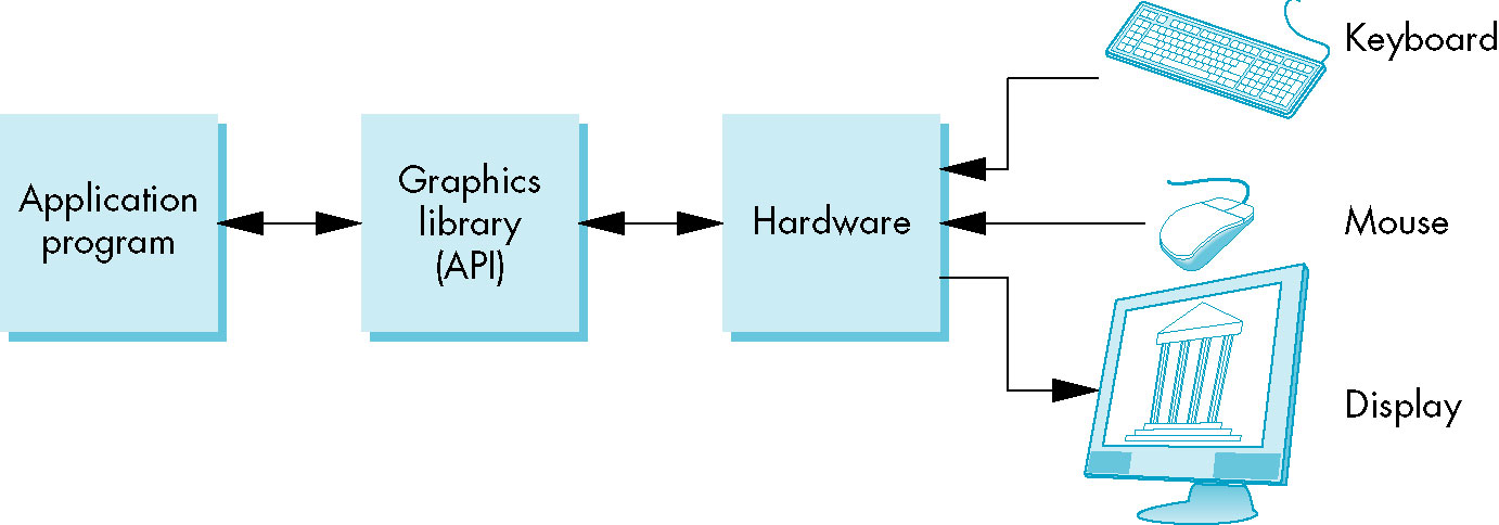
- Structure of a graphics program:
- Application program (what you will be writing when you work with OpenGL
- Graphics library (application program interacts with it through the API)
- Software drivers for communicationg with specific graphics hardware
- The API presents a particular model of image manipulation and display which may or may not be conducive to
a particular imaging application.
Pen-Plotter Model
- Two dimensional
- Early form of graphics system
- Essentially a pen capable of moving in two directions on a piece of paper as well as being raised/lowered to the
paper surface.
- Basic primitives
moveto(x, y) move to specified location with pen raised
lineto(x, y) move to specified location with pen lowered
- Three dimensional images can always be projected onto the surface but the computation of the projection
is the user's-- rather than the system's-- responsibilty.
- Postscript is based upon this model.
- Alternatively, a raster/pixel-based system can be used:
writePixel(x, y, color) set specified pixel to specified color
- Useful for images (pictures)
- rasterization algorithms easily written using this system
3D APIs
- Based on synthetic camera model
- API has functions for
- objects
- typically specified via vertices
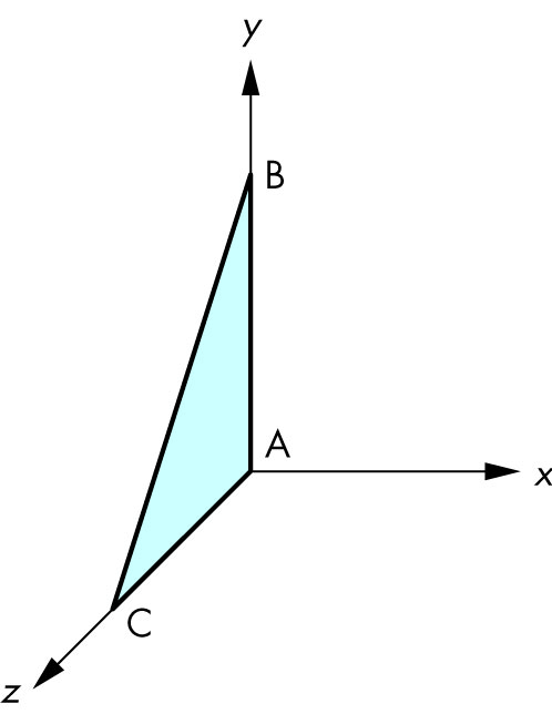
- geometric objects are easily specified in this manner
- objects that are so specified (and can thus be quickly display) typically form the
primitives of the API
- viewer (camera)
- position center of projection
- origin of camer'as coordinate system
- orientation
- rotation around the origin along one or more axes
- focal length
- The point at which rays entering the lens focus to a single point
- film plane
- where its located relative to the lens/center of projection
- light sources
- location
- strength
- color
- directionality
- material properties (e.g., textures)
Some of the Functionality of the OpenGL System
- wireframe
- geometric object generation
- transformations (2D and 3D)
- polygonal rendering
- hidden-surface removal
- etc...
The Modeling-Rendering Paradigm
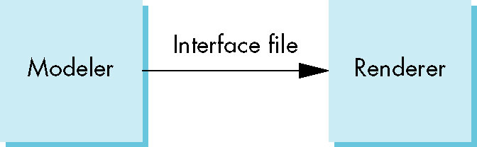
- Specification of the image (modeling) and generation of that image (rendering) handled as two
distinct tasks.
- Different needs, software and hardware requirements
- Creating the model highly interactive and graphical
- Rendering the image requires heavy processor use
- This paradigm allows for great flexibility
- Different modellers mapping to same rendering engine
- Sending same model to different rendering engine
- Similar to having multiple high-level languages compile to same intermediate code
- Various and complex data structures for representing the model and passing its specs to the
rendering engine
Graphics Architectures
Earliest form
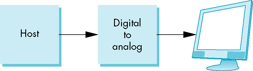
- Before specialized arhictecture was employed
- Processing side was standard CPU which calculated endpoint of lines in image
- Vector-based display -- capable of drawing line segment between two arbitrary points on display
- Maintaining a reasonable refresh rate was a challenge
Display Processors
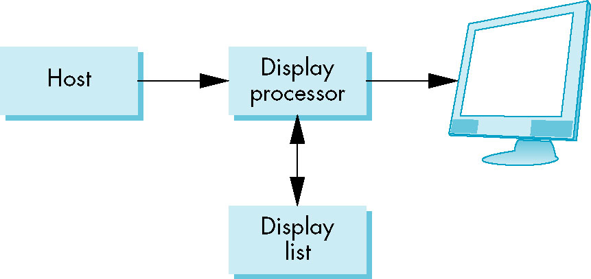
- Independent display processor
- Took care of refreshing image (resending it to display device), relieving primary CPU
of that task
- Convemtional hardware with possibly a few additional display primitives
- display list/file used to convey image data from primary CPU to
display processor
- Fits in nicely wit a client-server architecture
Pipeline architectures

- Image specs passed down a pipeline (essentially an assembly line of
tasks, each performing some action on the image).
- Idea originated in chip design
- Machine-level instructions are broken into smaller operations which are performed one after the other
- At any one point in time multiple (machine-level) instructions are at differnet points in the pipleline
- This provides a significant increase in throughput
- Translated to graphics processing:
- Start with the vertices (line segment endpoints and possibly intersections) of the objects in the image
- Vertex processing
- Perform coordinate transformations on each vertex
- Several levels of transformation - object space to various intermediate coordinate systems
(representing transformations such as scaling or rotation) to viewer space to projection
- 4 x 4 matrices are used and combined - operations are now burned into the chip
- These operations can be pipelined and parellelized
- Determine pixel's color
- Simple or realistic lighting-based color
- Clipping and primitive assembly
- Field of view is limited and thus clipping must be performed.
- Furthermore, clipping is done on an object (rather than vertex) basis, so objects (represented as related groups of
vertices) are assembled in this step as well.
- A vertex lying outside the image does not mean that the entire image is not displayed
- Rasterization
- converting the vertices into frame buffer pixels (e.g., setting
pixels corresponding to the line segment between a pair of endpoints; settig pixels within the area
of a polygon specified to be filled).
- Output is a set of fragments corresponding to information about a pixel that may eventually
be displayed (or not depending on depth and other hidden surface removal information)
- Fragment processing
- hidden surface removal
- Color alteration due to textures, blending, translucency
- Effect of this step is to update the pixels in the frambe buffer prior to final display