CIS 41
Computer Graphics
Chapter 4 - Geometric Objects and Transformations
Goals
- Get somewhat of an appreciation of the mathematical machinery of
a modern graphics system
- This understanding is helpful and sometimes necessary in order to work in such a system
The Basic Elements of Geometric Objects
- Scalars
- Points
- Vectors
- Everything else built up from those
- We'll present them from a mathematics perspective,; however we can also think of implementing
them as data structures (with acceptable values and operations).
Scalars
- Numbers with the following properties:
- addition/multiplication
- inverses (and thus subtraction/division)
- commutative, associative, distributive
- No geometric properties
- Used to express values such as distances
- lowercase letters from the beginning of the alphabet; lowercase Greek letters
- Forms a scalar field
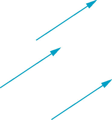
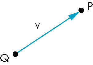
Vectors / Vector Spaces
- Magnitude and direction
- Can be thought in terms of directed line segments
- length is magnitude
- orientation is direction
- No position
- zero vector
- Zero length, no direction
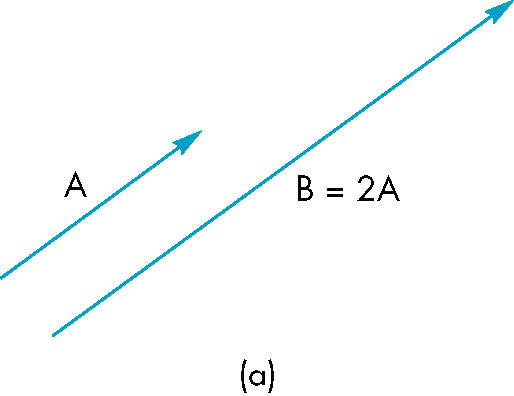
- Vector-Scalar multiplication
- w = kv
- results in a vector with same (or opposite) direction and original magnitude multipled by the scalar
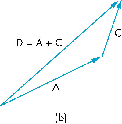
- Vector addition
- w = u + v
- uses head-to-tail axiom
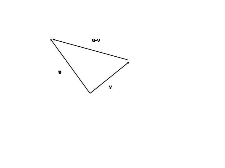
- Vector subtraction
- w = u + v
- uses tail-to-tail
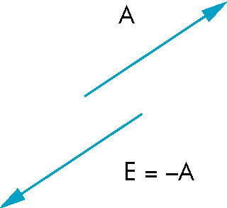
- inverse of a vector
- -v
- When aded to vector, produces zero vector
- same magnitude opposite direction
- Expression using the above operations
- v = u + 2w - 3r
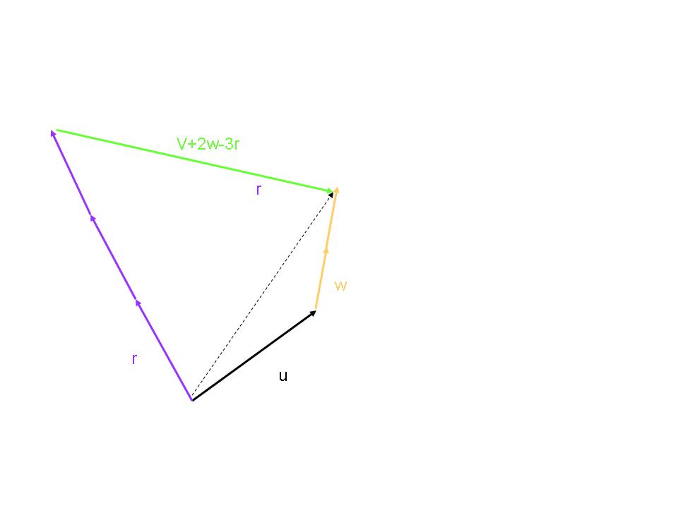
- lowercase letters from the end of the alphabet
- Together with scalars forms a vector space
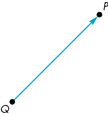
Points / Affine Spaces
- Location in space
- Point-point subtraction
- equivalent to point-vector addition
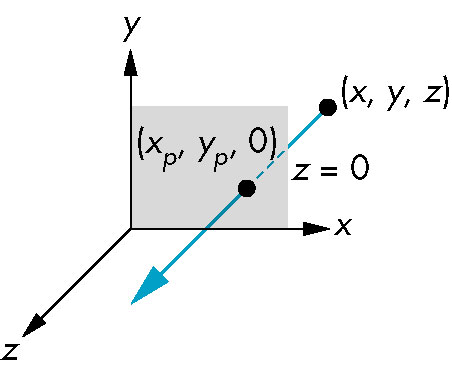
- Leads to the notion of a line:
- All points of the form P(a) = P0 + αd where
- P0 arbitrary point
- α is a scalar that ranges over a set of values
- d is an arbitrary vector
form a line
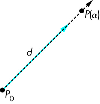
- The above is called a parametric form of the line
- It's simple to generate points on the line-- simply iterate through α
- Back to circle
- explicit - y2 = r2 - x2
- Implicit - x2 + y2 = r2
- parameteric - x = cos(θ), y = sin(θ)
- For line:
- explicit - y = mx + b
- Implicit - ax + by + z = 0
- parameteric - P(a) = P0 + αd
- P0 is the point for which α is 0.
- For α > 0, the line extends to infinity in the direction of d
- That directional infinite line is known as a ray
- Uppercase letters
- Added to vector space forms an affine space
Linear (In)dependence
- A set of vectors are linearly dependent if one of them can be expressed in terms of
the others
- Given vectors
v1 = [0, 0, 1]
v2 = [0, 2, -2]
v3 = [1, -2, 1]
v4 = [4, 2, 3]
- The first three are linearly independant
- The fourth can be expressed in terms of the others
v4 = 9v1 + 5v2 + 4v3
- This shouldn't be surprising as this is a 3D vector
- No more than three vectors can be linearly independent in
three dimension
- In real life (3D), you never need to more than three directions--
e.g. how far north/south, east/west, and up/down. Any further information
is superfluous.
- Those directions are exactly vectors (magnitude and direction)
- If no such combination can be found the vectors are said to be
linearly independent
Basis
- As referred to above, 2D/3d/4d vector spaces can have at most 2/3/4 linearly independent
vectors
- A set of such vectors is called a basis.
- Any vector in the space may be expressed in terms of the basis vectors
w = α1v1 + α2v2 + α3v3
- The scalars, αi, are called the components of the vector w
wth respect to the basis v1, v2, v3.
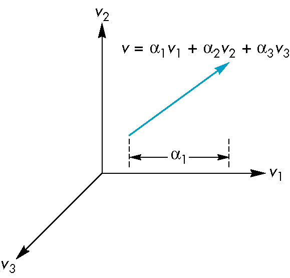
- Think if each component as the effect the corresponding vactor of the basis has upom the resulting vector
- In our above example:
- α1 is the effect v1 has on w
- α2 is the effect v2 has on w
- α3 is the effect v3 has on w
- We typically write the components as a column vector
   | α1 |
   | α2 |     let's call this a
   | α3 |
and this is known as the representation of the vector with respect to the basis.
- The transpose of a column vector is the corresponding row vector containing the
same components in the same order. Thus:
| α1 | T
| α2 | = | α1  α2 α3 |
| α3 |
- We often also write the express the relationship between the α's and v's as:
             | v1 |
   |α1 α2 α3| | v2 |  = α1v1 + α2v2 + α3v3
             | v3 |
i.e., using a row vector for the α's.
- If we restrict ourselves to talking directly about columns vectors, then we write the above as
aTv
- And we can think of the above as multiplying two vectors
Coordinate Systems
The vectors of a basis form a coordinate system.
- Informally, you can think of the basis as a set of standard compass directions
- Imagine swapping North and South (equivalent to reversing the direction of say the z-axis). Can still give
directions, just differently.
- However, such a system has no notion of position-- only magnitude and direction.
- Thus, placement of the vectors ANYWHERE, does not change whatever information we have
- Leaving us with no concept of a point
Frames
Moving from Vectors to Numbers
Given
v = α1e1 + α2e2 + α3e3
where e1, e2, e3 form the basis, the representations of e1, e2,
e3 themselves (with respect to
e1, e2, e3) is:
e1 = (1, 0, 0)
e2 = (0, 1, 0)
e3 = (0, 0, 1)
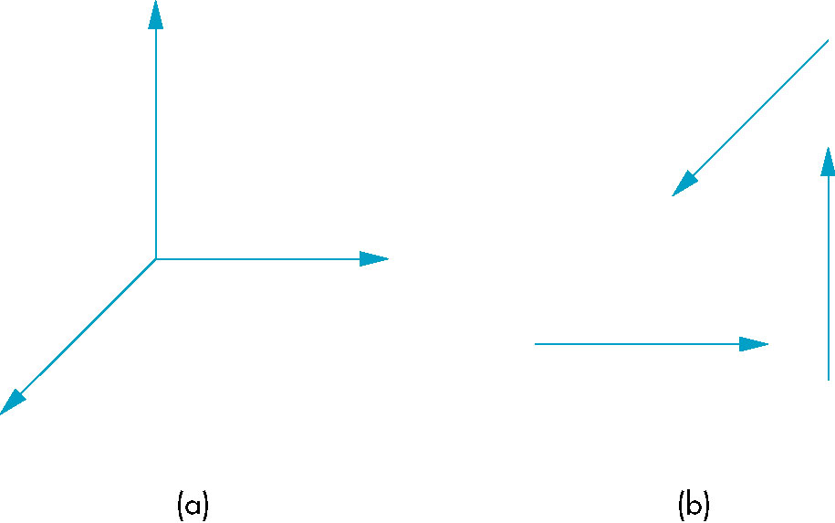
- Visualize three linearly independent vectors in 3D space.
- Your notion of them involves some reference of them with
respect to the origin.
- Think of them as colored lines and your coordinate axis ((*,0,0) for
the x-axis, (0,*,0) for the y-axis, and (0,0,*) for the
z-axis) are solid black
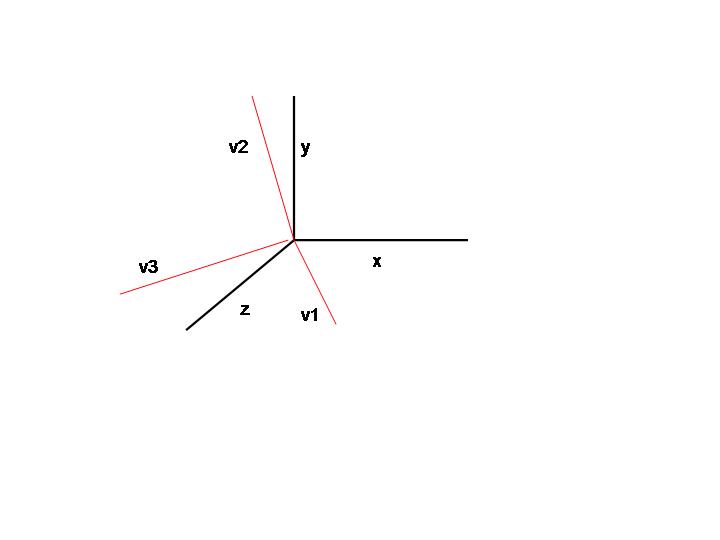
- Now rotate the axes until they coincide
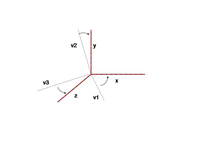
- the three vectors have now become the axes and from their point of view, they are (1,0,0),
(0,1,0), and (0, 0, 1)
manipulating sequences of numbers (tuples) is easier and more efficient than
trying to work with some other representation of a vector
Changing Coordinate Systems
- Basic question is what happens to the representation of a vector when
we change basis.
- This has practical significance to us
- Want to employ various frames at particular parts of the pipeline
- object/model frame
- Frame whose origin and directions (coordinate system) is relative to a particular object
(say center of car)
- Objects are eventually moved to the world frame
- We then shift to a system centered around the camera, the camera/eye frame.
- Each of the above involves a change of coordinate system/frame.
- The above sequence object->world->camera is perfomred by the model-view matrix
Changing Representations of Vectors
- Given bases {v1, v2, v3} and {u1, u2, u3}.
- Each vector from the second basis can be expressed in terms of the three vectors of the first
and vice versa
- That's what it means to be a basis-- all other vectors can be described by the elements of the basis
u1 = γ11v1 + γ12v2 + γ13v3
u2 = γ21v1 + γ22v2 + γ23v3
u3 = γ31v1 + γ32v2 + γ33v3
- If we isolate the components of the ui's, we get
| γ11 γ12 γ13 |
| γ21 γ22 γ23 |     let's call this M
| γ31 γ32 γ33 |
- As mentioned before, if we examine this, we see that γi,j is
the effect the basis vector vj has upon ui in this representation
- Thus:
- γ1,1 is the effect of v1 on u1
- γ2,3 is the effect of v3 on u2
- We might then employ something like what we did before for a single vector:
           | v1 |
|&alpha1 &alpha2 &alpha3|  | v2 |  = &alpha1v1 + &alpha2v2 + &alpha3v3        - i.e., &alphav
           | v3 |
but this time do it for the three basis vectors, giving us:
| γ11 γ12 γ13 |  |v1|   | γ11v1 + γ12v2 + γ13v3 |   | u1 |
| γ21 γ22 γ23 |  |v2| = | γ21v1 + γ22v2 + γ23v3 | = | u2 |       - i.e., u = Mv
| γ31 γ32 γ33 |  |v3|   | γ31v1 + γ32v2 + γ33v3 |   | u3 |
- The 9 γi,j values contain all the information needed to get from the representation of the vector in one basis to
a representation in a second.
- (We also would like to go in the other direction as well- we would like an inverse transformation)
- Now consider a vector w with the representation in basis {v1, v2, v3} of
w = α1v1 + α2v2 + α3v3
- We have (as before):
   | α1 |
   | α2 |   let's call this a
   | α3 |
and:
             | v1 |
   |α1 α2 α3| | v2 | ( = α1v1 + α2v2 + α3v3) - i.e., aTv
             | v3 |
- Now suppose w had a representation in basis {u1, u2, u3} of
w = β1u1 + β2u2 + β3u3
- We have (as before):
   | β1 |
   | β2 |   let's call this b
   | β3 |
and:
             | u1 |
   |β1 β2 β3| | u2 | ( = β1u1 + β2u2 + β3u3) - i.e., bT u
             | u3 |
- And now we have
w = bTu = bTMv (because u = Mv)
and
w = aT v
leaving us with:
aT = bTM
Ok, Now What-- What Does this Leave us With?
Matrices and Matrix Multiplication
- As we saw, we maintain this transformation in the 3 x 3 arrangement
| γ11 γ12 γ13 |
| γ21 γ22 γ23 |     let's call this M
| γ31 γ32 γ33 |
- This arrangement is known as a matrix and is the central element of the transformation
capability
- Furthermore, the calculation
| γ11 γ12 γ13 |  |v1|   | γ11v1 + γ12v2 + γ13v3 |   | u1 |
| γ21 γ22 γ23 |  |v2| = | γ21v1 + γ22v2 + γ23v3 | = | u2 |       - i.e., u = Mv
| γ31 γ32 γ33 |  |v3|   | γ31v1 + γ32v2 + γ33v3 |   | u3 |
which reflects the effect of the transformation on a vector, is defined to be the operation matrix multiplication
Trying to get a feel for a (2D) Matrix
Suppose we have a matrix:
| γ11 γ12|
| γ21 γ22|
and we multiply it by the two standard basis vectors
|1 0| | γ11 γ12|  -> | γ11 γ12|
      | γ21 γ22|
and
|0 1| | γ11 γ12|  -> | γ21 γ22|
      | γ21 γ22|
we thus see that the rows of the matrix correspond to the standard basis vectors after the transformation
represented by the matrix.
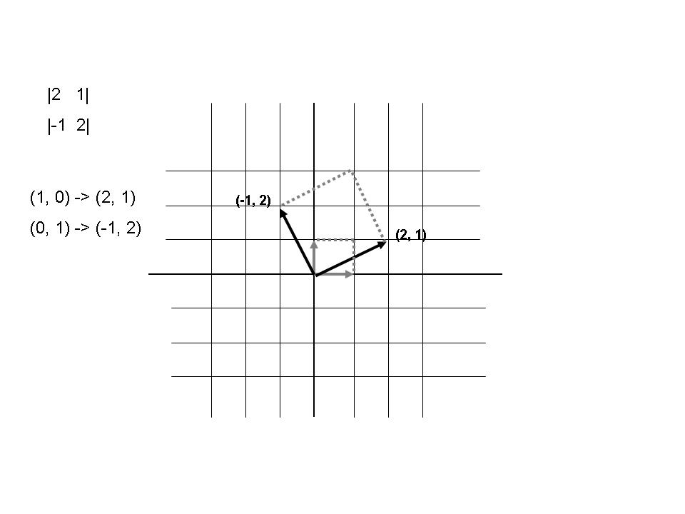
We can visualize the effect of the matrix. The following shows the effect of the matrix
|2  1|
|-1 2|
Frames in OpenGL
Frame changes, as it turns out, are central to what we want from the graphic pipeline.
Returning to the (relative) coordinates that appear in the pipeline:
- Object or model coordinates
- >World coordinates
- Camera (eye) coordinates
- Clip coordinates
- Normalized device coordinates
- Window (screen coordinates
Model-View Transformations
Tracing this sequence in more detail:
- A vertex is specified via
glVertex
- These coordinate may be specified in a global frame (world coordinates)
or in a frame local to a particular object being drawn
- There may actually be a hierarchy of such object's (remember the discussion
glPushMatrix and of drawing
a nose on a face-- each nested object had its own (relative) frame/coordinate system.
- At some later point we wish to bring all the individual objets with their local frames into the world frame-- converting
the local object coordinates into world coordinates
- World and object coordinates will be different only if some transformation (for example a rotation0 is performed before
drawing the vertices of the objet.
- The world frame/coordinates form the entire picture; they are then transformed into the camera frame which composes the picture
(for example the angle at which the viewing is being done)
Each of the above change of frames is represented by a transformation matrix
- The sequence of transformations are concatenated into a single model-view transformation.
This is done by multiplying the individual transformation matrices into a single matrix known as the
model-view matrix.
Projection Transformations
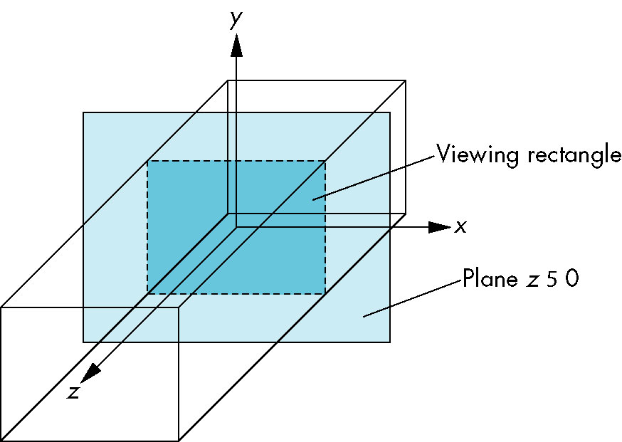
At this point a further set of projection transformations occur:
- The eye coordinates are trnasformed into clip coordinates which allow the system to determine which objects (or portion thereof) lie outside the
clipping/viewing volume.
- A perspective division is performed (basically applying standard rules of perspective (more on that later)
resulting in normalized device coordinates
- The normalized coordinates are transformed into window coordinates which still retain depth information but use the coordinate
system of thedisplay device.
- Screen coordinates are then obtained by stripping out depth information
Affine Transformations
- Transformation that preserves lines
- Central to efficient transformations
- Only need to transform endpoints-- eveything in between follows propely with subsequent line generation
- Avoids transforming EVERY pooint on line
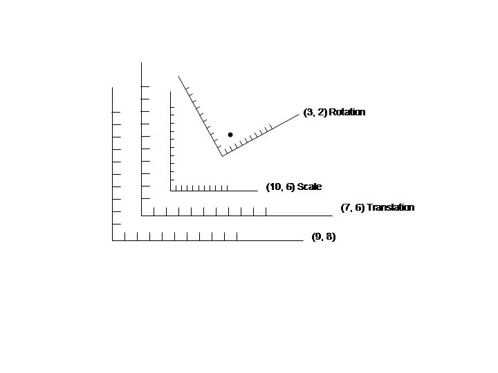
The Basic Transformations
- Interested in representing the transformations as matrices/vectors which can then be combined
Translation
- New point is obtained by adding a displacement vector to the original point
P' = P + d
- This can be reflected via simple vector addition
Rotation
- Transformation matrix in 2D (rotation around origin)
| cos θ   -sin θ |
| sin θ   cos θ  |
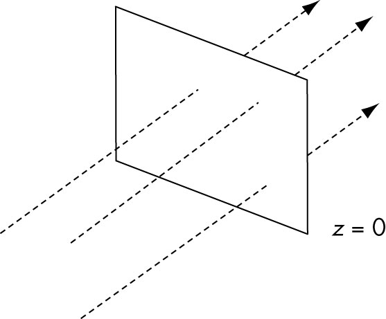
- Rotation in 2D is around a single point
- Rotation in 3D is around a line(vector)
- 2D rotation in z = 0 plane translates to 3D as rotation around z-axis.
- 3D rotations around the standard axes:
| cos θ   -sin θ  0 |
| sin θ   cos θ   0 |     Rotation around z-axis
| 0       0       1 |
| 1      0       0  |
| 0  cos θ   -sin θ |
| 0  sin θ    cos θ |     Rotation around x-axis
| cos θ   0   -sin θ |
| 0       1        0 |       Rotation around y-axis
| sin θ   0    cos θ  |
- Rotation around an arbitrary vector
- Combination of three rotations (around standard axes)
- Euler angles
Rigid body Transformations
- Shape and volume of object remains unchanged
- Includes rotation and translation
Scaling
Homogeneous Coordinates
- Allow translation to be expressed as matrix multiplication result
- Also differentiates between point and vector
- Add a fourth coordinate to a vector and point
- Add additional row/column to matrix
Rotation
| cos θ   -sin θ  0 |
| sin θ   cos θ   0 |
| 0       0       1 |
| cos θ   -sin θ  0   0 |
| sin θ   cos θ   0   0 |     Rotation around z-axis
| 0       0       1   0 |
| 0       0       0   1 |
| 1      0       0    0 |
| 0  cos θ   -sin θ   0 |
| 0  sin θ    cos θ   0 |     Rotation around x-axis
| 0       0       0   1 |
| cos θ   0   -sin θ   0 |
| 0       1        0   0 |       Rotation around y-axis
| sin θ   0    cos θ   0 |
| 0       0       0    1 |
Scaling
| Sx   0  0 |
| 0    Sy 0 |
|0     0  1 |
| Sx   0   0   0 |
| 0    Sy  0   0 |
| 0    0   Sz  0 |
| 0    0   0   1 |
Translation
| 1  0  dx |
| 0  1  dy |
| 0  0  1  |
| 1  0  0  dx |
| 0  1  0  dy |
| 0  0  1  dz |
| 0  0  0   1 |
Transformations in OpenGL
- OpenGL uses homogeneous coordinates (i.e., point are 4x1 column vectors and matrices are 4x4)
- Current transformation matrix (CTM)
- Transformation matrix applied to any subsequently specified vertex
- Homogeneous (4x4) matrix
- Initially set to identity matrix I
- Given C as the CTM, and point p, we get
Cp
- OpenGL uses postmultiplication of the CTM only
- Given CTM C, applying an addition transformation matrix, T produces
CT
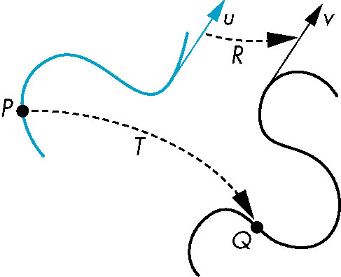
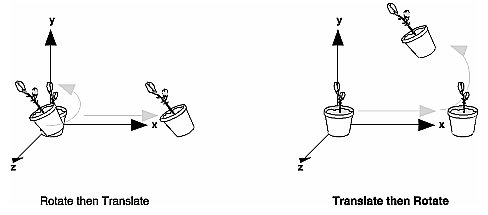
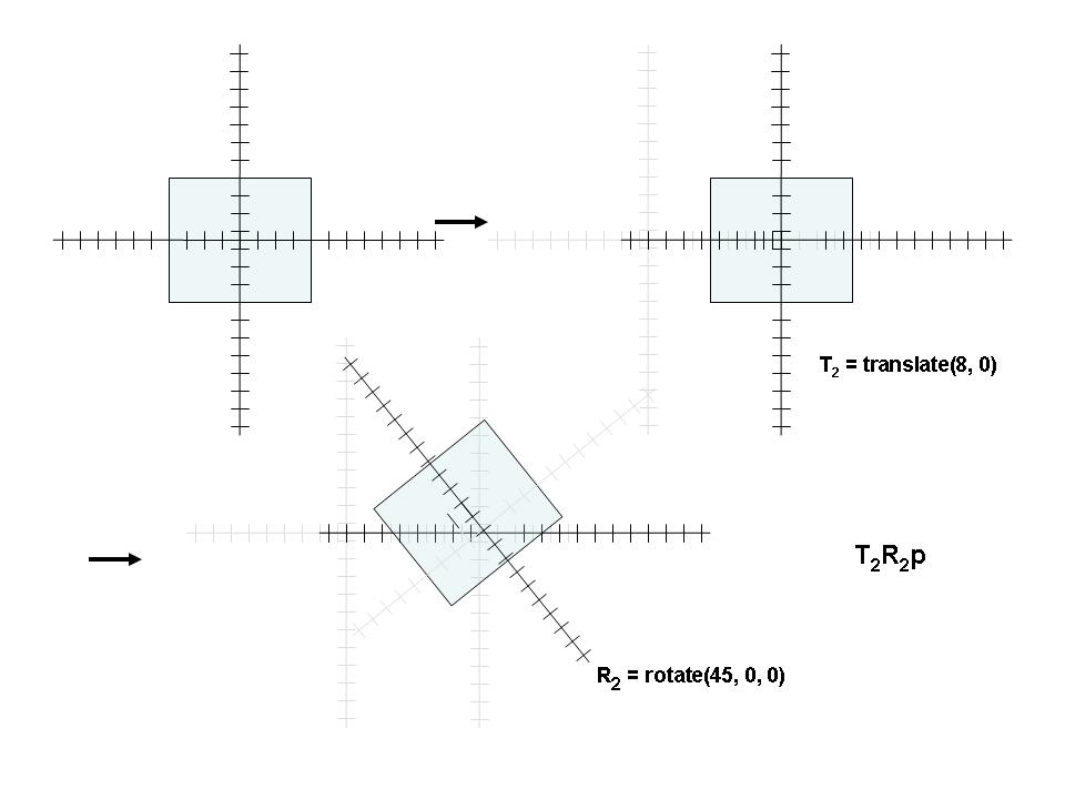
- Given Transformations R and T to be applied to the point in that order, we want:
TRp
- Since most transformations DO NOT commute (TR != RT), we must be careful of the order
- Furthermore, as we see above, the order of appearance is the reverse
of the order of application.
The OpenGL Transformation Functions
glScalef(scaleX, scalEY, scaleZ);
glTranslate(dx, dy, dz);
glRotate(angle, vbx, vy, vz);
Thinking About Transformations
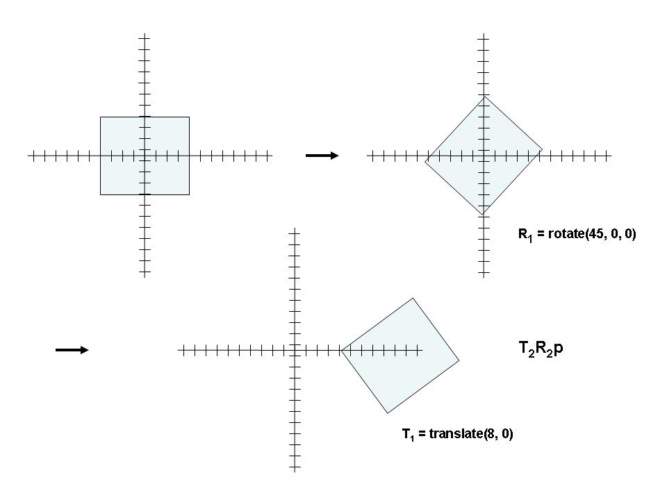
- Transformations typically don't commute
- One therefore has to be careful about the order in which they are specified
- OpenGL treats points as column vectors and thus the point is to the right of the transformation
sequence
- The point is said to be premultiplied by the transformation matrices
- This means the last transformation is applied first (equivalently, the transformations are applied in reverse
order of appearance).
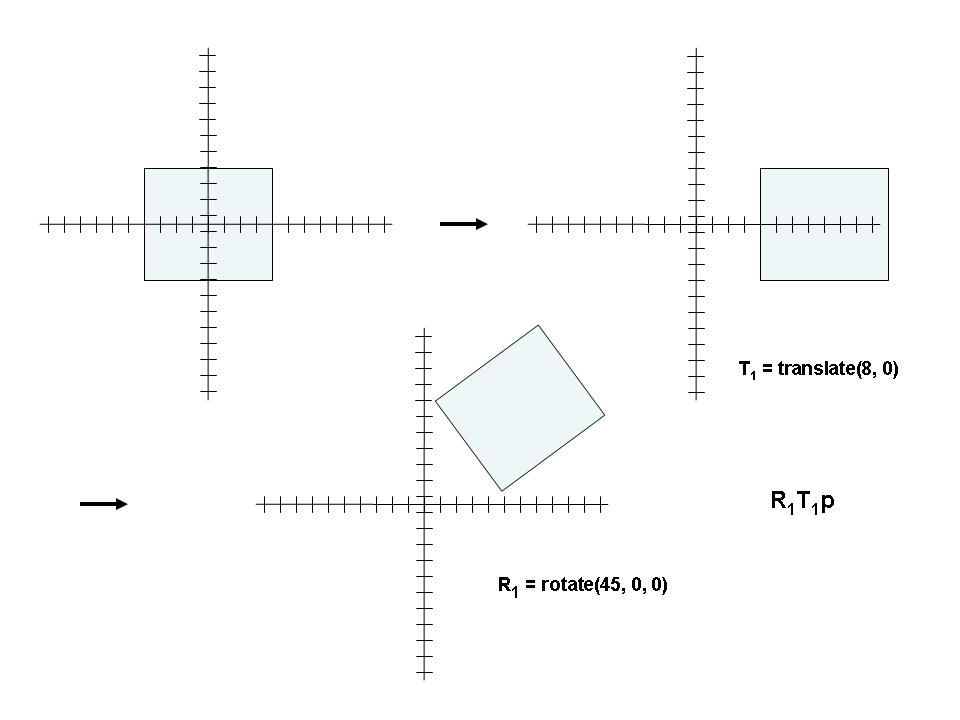
Thinking of Everything Relative to a World Coordinate System)
- We're thinking of the point being transformed:
p' = Mp
- With multiple transforms, each is applied to the previous result:
p' = M1M2p
- The order of appearance is thus the reverse of the order of application
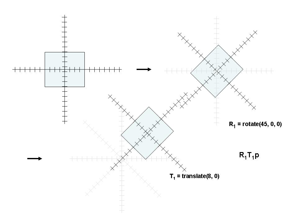
Thinks of an Object's Local Coordinate System
- The object remains centered in its own local coordinate system
- The transforms in this visualization occur in the order of appearance
The code for both remains the same-- the difference is how you visualize the transformations!
So... If They're Both the Same, How are They Different?
- Use the grand coordinate system when the problem seems to have a natural grand coordinate syste,
- Our solar system example below is an example
- Use the local system if the problemis composed of parts each of which are easiest visualized in their own system
- The robot arm is a good example
Read the Section Viewing and Modeling Transformations / Thinking about Transformations
int Chapter 3 of the Redbook
The Planetary System Application
- Based upon Chapter 3 example from redbook
The ModelView Matrix
- Model view incorporates
- Model/Object-related tranforms
- think of it as the composition of the image
- sizes, relational poositions and orientation
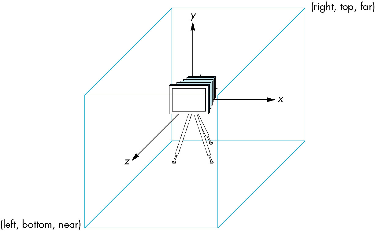
- Camera (eye) position
- Specified with three values
- Where it is (eye)
- Where its focused (center or look)
- Which way is up
- We think of it as composing the image then placing the camera
- Thus, by our LIFO order of transformation specification, the camera related functions
which are performed later appear first
- They're actually two sides of the same coin
- (think of having a camera bolted to the ground, no choice but to arrange the scene with
respect to the camera)
- Camera positioning can thus always be replaced by a sequences of translations, rotations and scalings
- Represented by a single current modelview matrix
- To select it, use
glMatrixMode with a GL_MODELVIEW parameter
- To save and restore, use and
glPopMatrix
The gluLookAt Function
- Nine parameters (not so bad thought-- really only three)
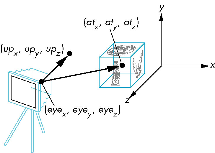
- x, y, z coordinates of camera position
- x, y, z of point (actually vector) of focus
- x, y, x of up vector
- This call is usually the first afer the glLoadIdentity (since
it should be applied last)
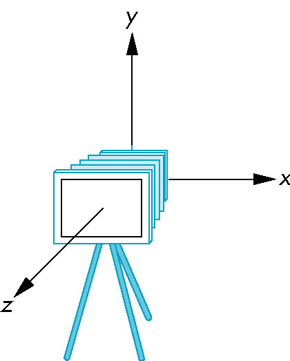
- Default is camera positioned at origin looking down negative z-axis
The Object-Oriented Version
Object-oriented version uses example of an instance transform
- Have an object (wire sphere in this case) whcich we are going to use repeatedly-- but with different
transform characteristics (size, orbital position, distance from world origin
- Store the specifics of the transformation with the object and apply whe displaying the object
The Robot Arm
- Helps to think of the coordinate system (rather then the object) moving.
- Transformations are then viewed as occurring in their order of appearance in the OpenGL code
- Easier to visualize positioning the hand with respect to the forearm (rather than independently (i.e., with
respect to the shoulder joint)
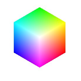
The Spinning Color Cube
- To get a color cube (or any multi-colored cube), can't use
glutWireCube
- Need to be able to specify individual face's colors
- The gradual color shading is done automatically and is called smooth shading
More on Smooth Shading
- Colors are maintained at the vertices only, the polygon faces are then filled in using a polygon-filling
algorithm (Chapter 7).
- The shading model is specified using the
glShadeModel method
- The paramater
GL_SMOOTH or GL_FLAT specifies which model to use
- In flat mode, the color from one of the vertices is extended to the entire face

- In smooth mode, the colors for the faces are interpolated by OpenGL
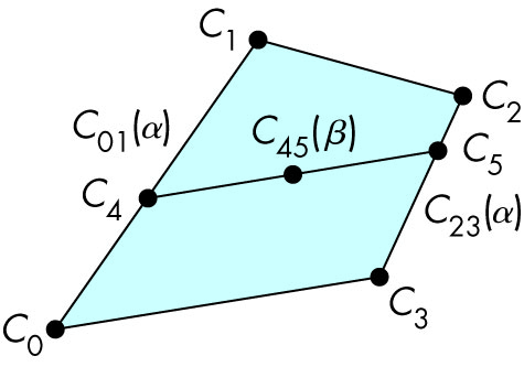
- Blend the colors C0, C1 along the connecting line producing C01(α);
and similary blend C2, C3 producing C23(α); (i.e., loop along the line using
the index variable α which ranges from 0 to 1 -- the color will 'morph' from the color at C0 to
C1; similarly for the C2-C3 line).
- At corresponding points C4 and C5 along the C0-C1 and
C2-C3 lines respectively (i.e., for the same values of α), interpolate again along
the connecting line to produce the actual color point C45(β)