Sequential Circuits: SR Flip-Flop
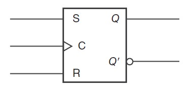
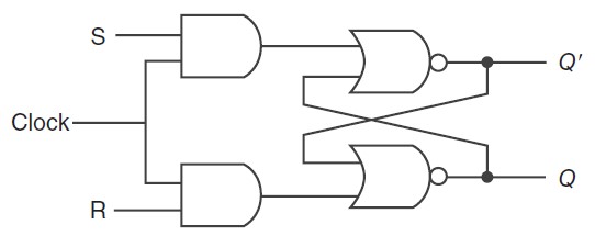
The SR (Set-Reset) flip-flop has two inputs: S (Set) and R (Reset).
When S is activated ($1$) and R is deactivated ($0$), the flip-flop sets its output to $1$. When R is activated and S is deactivated, the output resets to $0$. If both inputs are $0$, the output retains its previous state. However, if both inputs are $1$, it creates an undefined or forbidden state.


