CIS 41
Computer Graphics
Chapter 5 - Viewing
Viewing
- Consists of two parts
- Positioning of the camera
- Second half of the synthetic camera model
- First half was specification of the object's/models of the image
- WHat we're looking at now is the positioning of the camera
- Various types of views, each with their own purpose
- Second deals with the size and shape of the portion of the image we wish to view
- The first specification becomes part of the modelview matrix; the second forms the
projection matrix
Classical/Computer Viewing
- Classical: views/Images as portrayed by artists and architects in the absence of computer graphics
- Still necessary to be generated
- Above professionals are now using software rather than classical drafting techniques
- Each such view serve a specific purpose in the respective field
- Have to be able to render these images using the graphics software
- Composed of
- Object(s)
- Viewer with a view plane (projection surface)
- Projectors (lines from object(s) to viewer-- straight lines
- Projection oin which the projection surface is a plane and the projectors are strainght lines are known a
planar projections
- Projectors extend from object through projection plane and meet at the Center of Projection (COP)
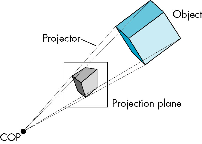
- center of camera lens or eyes
- In graphics system, origin of camera frame
- Increasing viewer-object distance to infinity causes the projector lines to become parallel
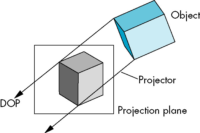
- COP then becomes replaced by direction of projection
- Leaving the projection plane in a fixed position does not affect image size on plane
- Projectors are no longer converging so position of plane from COP no longer makes a difference
- This leads to two basic families of projections
- perspective projections/views finite COP
- parallel projections/views infinite COP
- Camera frame origin usually lies in proection plane
- Both preserve lines, but not angles
- Are handled as separate cases (even though parallel is simply the limiting case of perspective).
- In classical views, the drafting techniques aew different
In graphics systems, different sets of projection matrices are used.
One Primary Difference Between Classical and Computer Viewing
- Classical viewing is concerned with the relationship between the view and the objects
- The views are caategorized by this relationsship
- Computer viewing keeps the objects completely independent of the viewer
- Think of the specification of the objects (with
GLVertex) together with
the transformations (e.g., glTranslate, in contrast with gluLookAt)
- Thus, the 'API' of classical viewing contains many more choices for viewing
- Obtaining such views in a computer graphics system may require calculation of the
corresponding relationship and properly orienting the camera to produce that relationship)
Classical Viewing
- principal face: objects are composed of planes
- think of how we draw a cube-- we specify six squares forming the surfaces/faces of the outside of the cube
- Each of those squares forms a principal face.
- CLassical viewing concerns itself with displaying the principal faces of an object in various orientations
- Might only show a single principal face
- Might show two or more
- The right angles where such faces meet provide opportunities for showing more than one side of an object at one
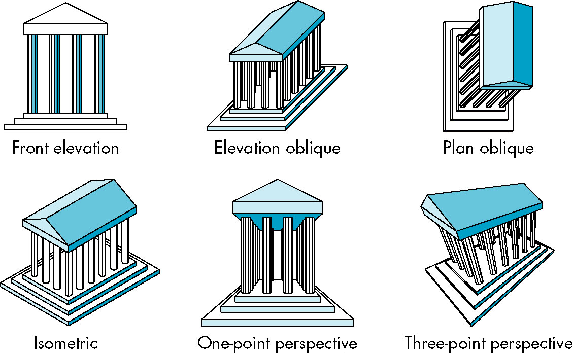
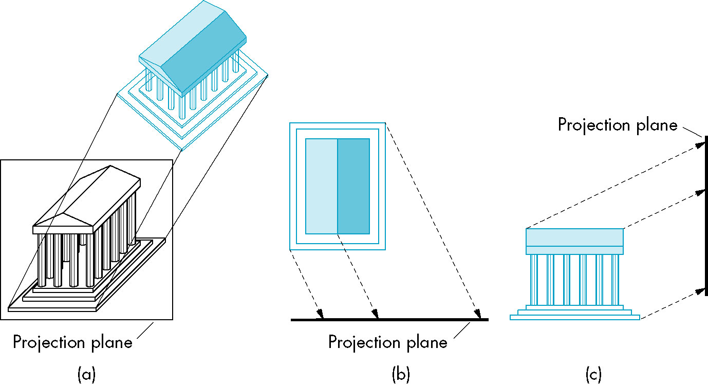
Parallel Projections
Orthographic Projections
- Projectors are perpendicular to the projection plane
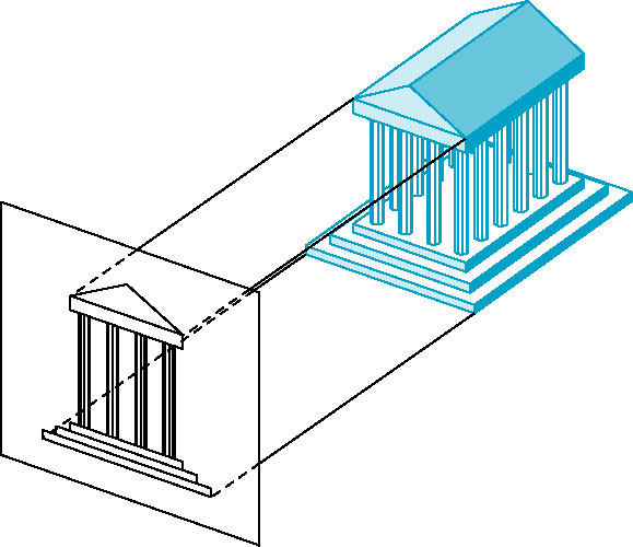
- multiview orthographic projection - more than one (orthographic) view of same object
- Each view has one of the principal faces parallel to projection plane
- Usually three views -- front, top, right
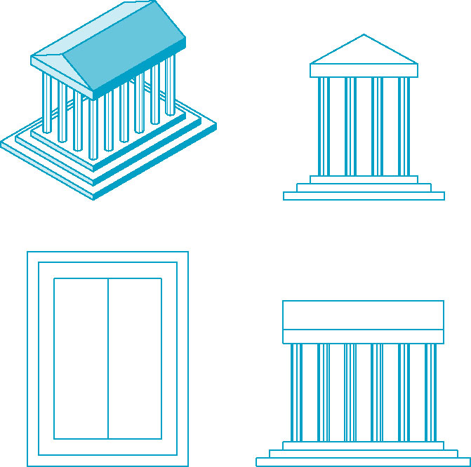
- Need multiple views to get sense of the entire object-- each view shows only one face
- No distortion of distance or angle
- Good for working architectural drawings
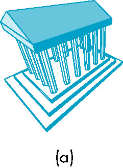
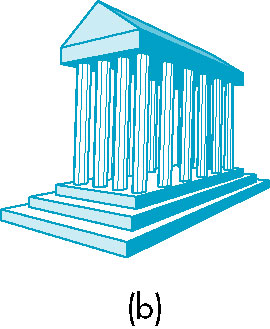
Axonomteric Projections
- Still have projectors perpendicular to projection plane, but now plane can have any orientation
with respect to object (no longer parallel to one of the faces).
- Plane is often positioned to show three adjacent faces of a cubelike object
- One of principal axes is usually chosen to be vertical
- Lines not parallel to the viewplane are foreshortened
- The visual effect that an object or distance appears shorter than it actually
is because it is angled toward the viewer.

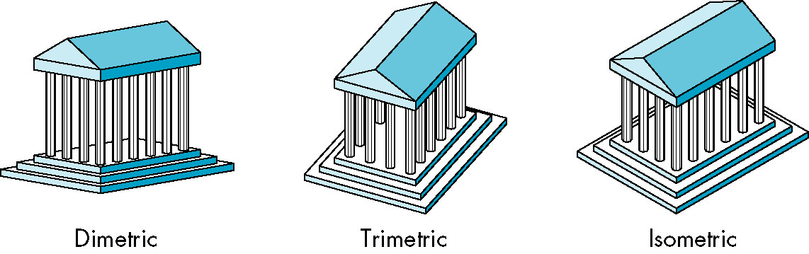
- Categories of axonometric projections
- Isometric (equal measures)
- All axes are foreshortend equally
- Still can take measuements
- Angles of all three corners of a projected cube are the same
- Angles between the axes are equal
- Dimetric (two measures)
- Two axes are foreshortend equally
- Angles of two corners of a projected cube are the same
- Angles between two axes are equal
- Trimetric (three measures)
- All axes are independent
- Angles of all three corners of a projected cube are different
- Advantages
- Even though foreshortening occurs, can still take measurements (using scaling factors)
- Lines are preserved
- Can see three faces simultaneously
- Disadvantages
- Angles not preserved
- Circles not parallel to projection plane not preserved (form ellipse)
- Looks artificial because of non-perspective (far and near objects are same size
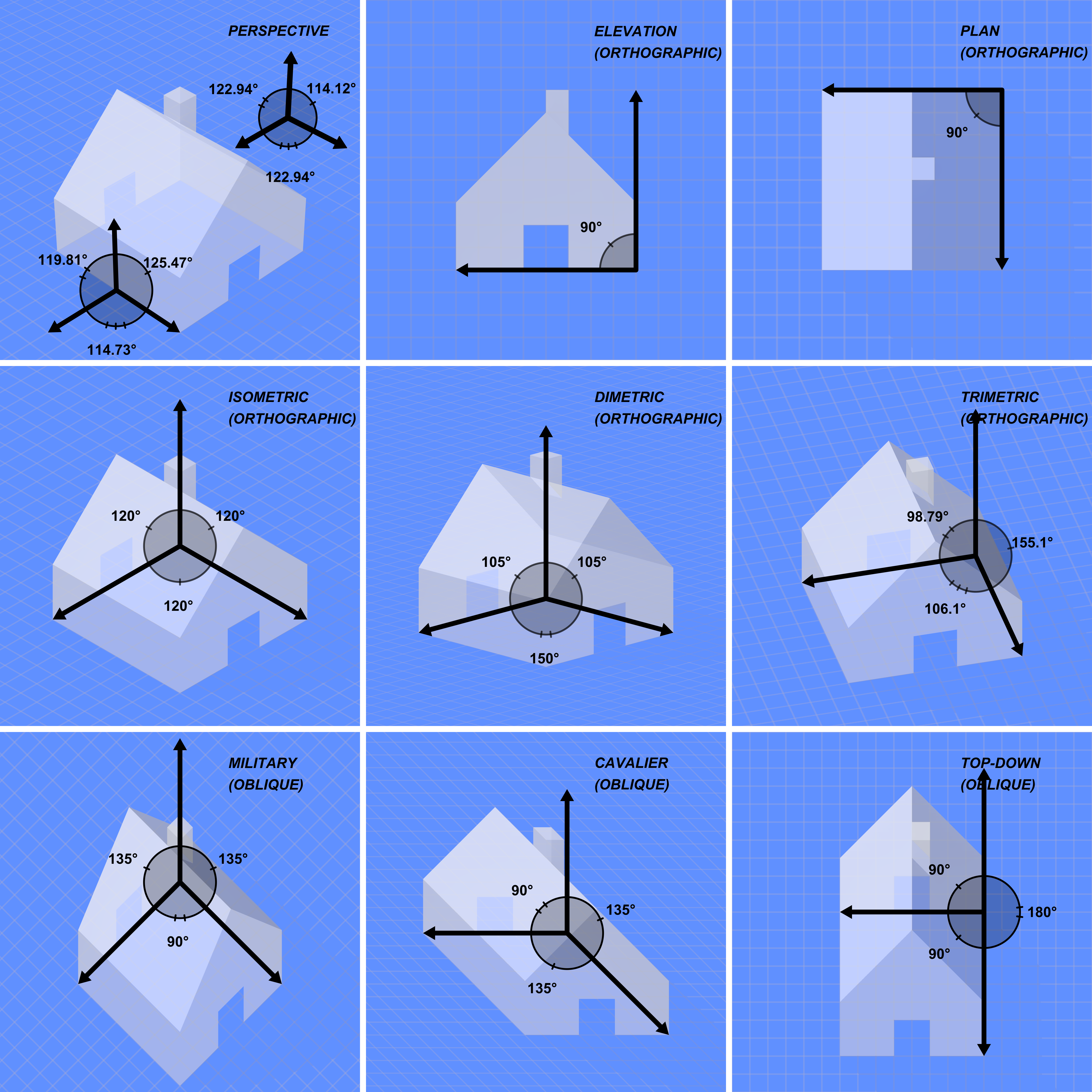
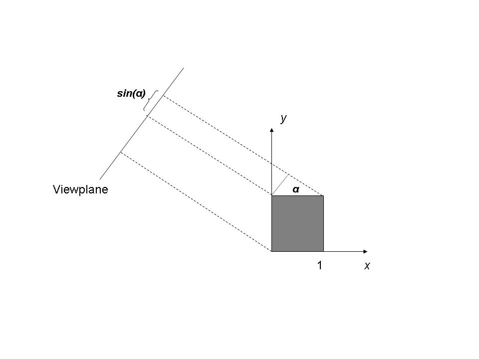
Oblique Projections
- Projectors can make arbitrary angle with projection plane
- From Wiki:
Oblique drawing is also the crudest "3D" drawing method but the easiest to master. Oblique is not really a
3D system but a 2 dimensional view of an object with 'forced depth'. One way to draw using an oblique view
is to draw the side of the object you are looking at in two dimensions, i.e. flat, and then draw the other
sides at an angle of 45 degrees, but instead of drawing the sides full size they are only drawn with half
the depth creating 'forced depth' - adding an element of realism to the object. Even with this 'forced depth',
oblique drawings look very unconvincing to the eye. For this reason oblique is rarely used by professional
designer and engineers.

- WRT to real world, requires a bellows camera to achieve
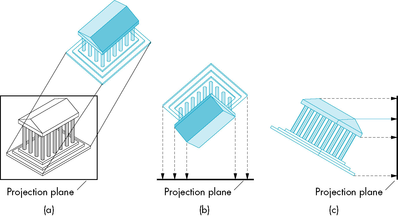
Perspective Viewing
- Projectors converge at COP.
- Diminuation of size of objects
- Objects further away appear smaller
- Provides a sense of realism
- Can't be used for measurement (foreshortening depends on viewer distance)
- Angles are preserved only in planes parallel to the projection plane
- Classical perspective has viewer symmetrically positioned wrt projection plane (eye perpendicular to center)
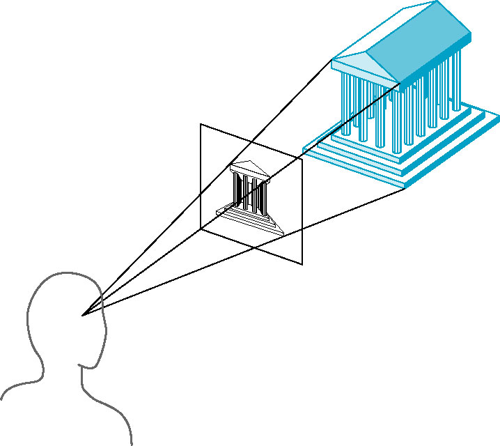
- Corresponds to our vision system and strcuture of a normal camera
- contrast with bellows camera above
- OpenGL's perspective API allows for general persepective (such as produced by a bellows camera)
One, Two and Three Point Perspective
- Refers to
- How many principal directions are parallel to projection plane (n-point has
3-n principal direction parallel)
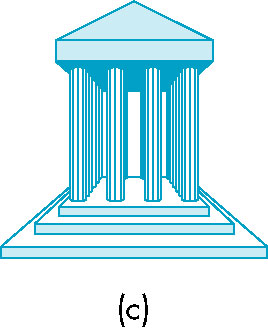
- How many vanishing points there are
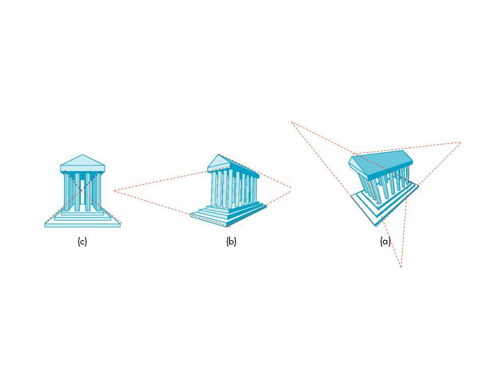
- Nothing more than specific orientations of general perspecive projection
Computer Viewing
- We should be able to obtain all of the classical views (and then some) using our synthetic computer model.
- However, that model maintains independence between the object and viewer
- Unlike classical as seen above which is based upon the relationship between the viewer and the image
- We can, in OpenGL, choose orthographic or perspective, but any further distinction is not part of the
API per say
- Knowledge of oblique, or two-point perspective, or isometric violates the view/object independence
- This makes placing the camera in a way that produces the proper classical project the responsibility of the
application program
Revisiting the Pipeline and Default Camera Placement
- Modelview first, involving
- Object placement
- Camera orientation
- Projection next, involving
- selection of orthographic or perspective
- Specifies shape of viewing/clipping volume
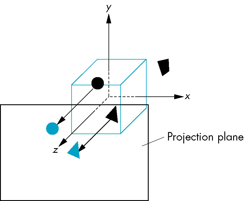
The Default Camera Orientation
- At origin facing negative z-axis
- Orthgonal projection
- Viewing volume 2 x 2 x 2 cube centered at origin
- projection plane of z=0
- direction of projection is along z-axis
Explicit Camera Positioning
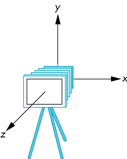
- Initially modelview matrix is identity matrix so object and camera frames are the same
- Since objects are usually positioned around origin, not all objects will be visible if camera is left
at default position
- We can either
(this is why camera positioning is incorporated in the modelview matrix)
- Moving the cameras (or equivalently the objects) results in two separate frames
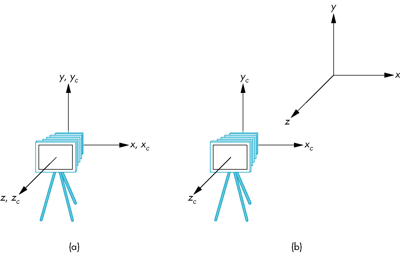
- The model view matrix thus contains the information to move between the two frames
- And again camera and object movement are equivalent so having this portion of viewing together with
object transformations makes sense
Positioning the Camera in OpenGL -- The gluLookAt Function
- Specify
- eye - origin
- look-at point (center) -- really a direction
- up direction
Projections
- Deals with camera properties rather than orientation
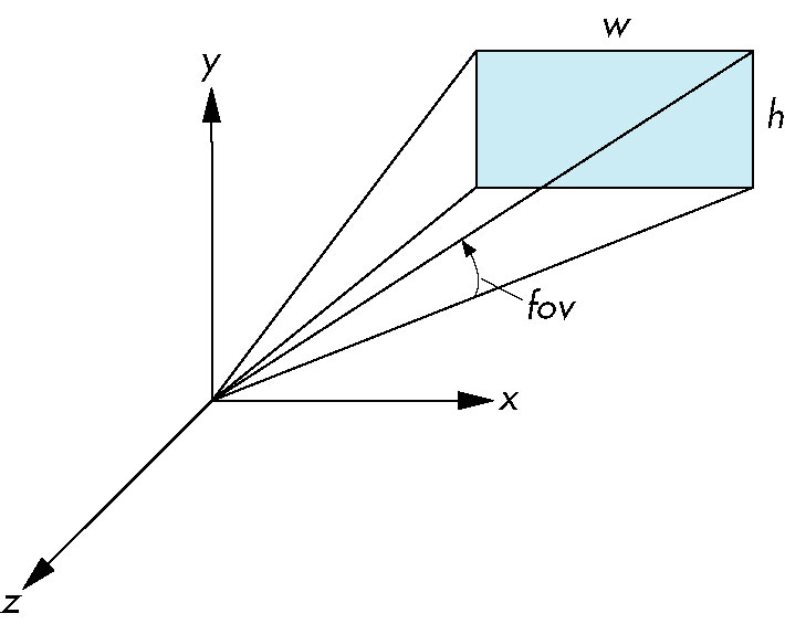
Perspective
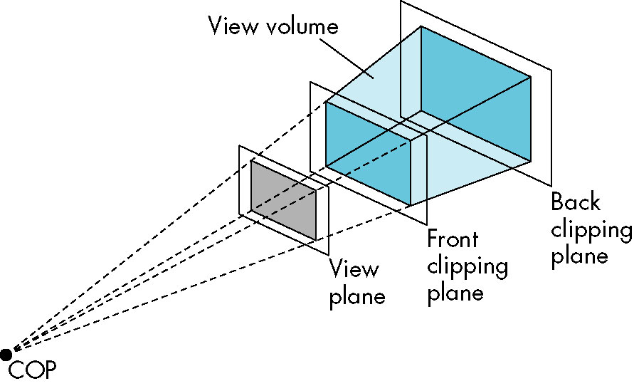
- angle of view - defines portion of world the will project onto viewplane
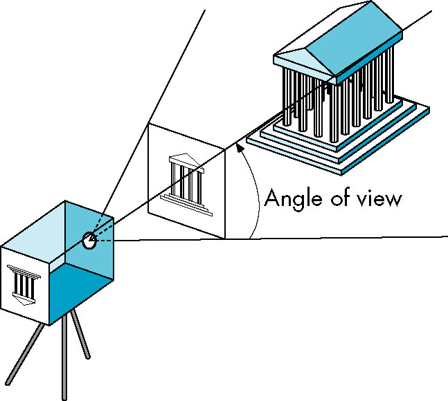
- view volume - the portion of the world that will appear in the image
- With a COP, forms an semi-infinite pyramid
- Object outside the view volume are clipped.
- Adding a front and back clipping plane to the viewing volume produces a frustum
- truncated pyramid
Perspective Projection in OpenGL - the glFrustum Function
- Same essential paramters as
glOrtho, except the planes are BOTH in front of the camera
lens (COP)
glFrustum(left, right, bottom, top, near, far);
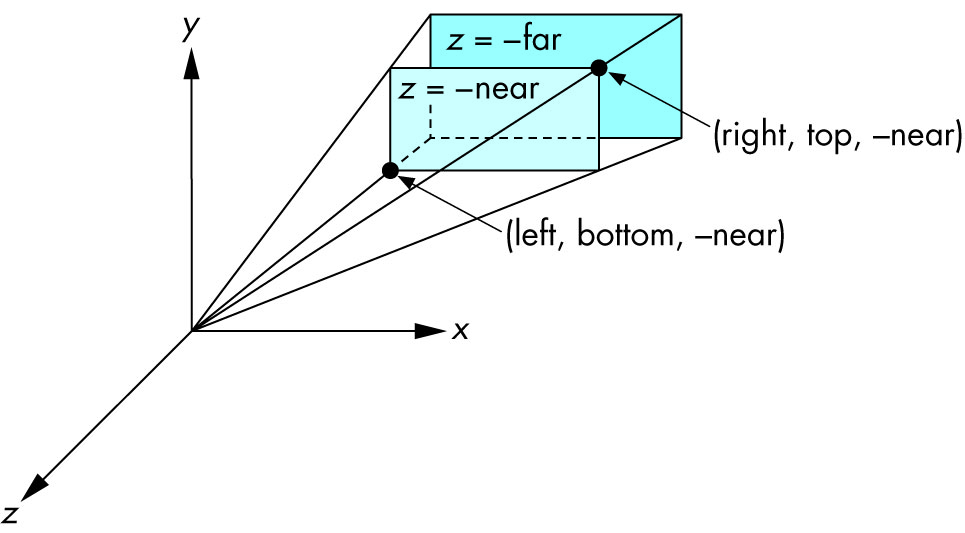
- Since we're facing negative z-axis, the actual locations are -near and -far
Perspective Projection in OpenGL - the gluPerspective Function
Parallel Projection in OpenGL - the gluOrtho Function
- Viewing volume is a parallelpiped
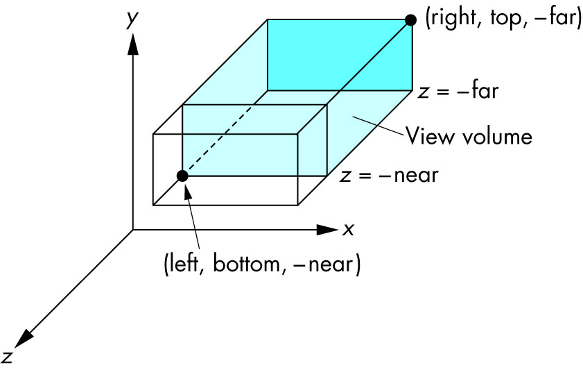
glOrtho(left, right, bottom, top, near, far);
Since we're facing negative z-axis, the actual locations are -near and -far
Code for Chapter 5