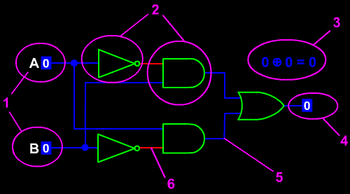
The
diagram and the legend presented below
are brought to explain how circuit and
gate demonstrations work in this tutorial.

1.
Inputs
These are clickable buttons. Once clicked,
input button changes color, its value
toggles from 0 to 1 and vice versa.
Toggling input value (sometimes in correct
sequence) triggers new state of logic
circuit.
2.
Logic Gates
Logic
gates are shown in green color. You
can learn more about basic logic gates
by reading the first
section of this tutorial.
3.
Calculation formula
Some
of animations presented in this tutorial
have a logic formula displayed, describing
the current status of logic circuit
or gate.
4.
Output
Output
symbols look exactly like input symbols.
There is only one difference - the output
symbols are not clickable and are shown
only to display resulting values of
a logic circuit or gate.
5.
"Wire - 0"
6.
"Wire - 1"
Logic
gates, input and output symbols and
other elements are connectd with read
or blue lines, representing electrical
wires. Red wire represents a wire currently
carrying a "1" signal, and
blue wire carries "0" signal.