Roverbot Construction Guide
Rover chassis
For more detail on the construction, click on the photos to view the
image full size.
Step 1
Start by picking out:
- two black 1 x 16 beams;
- two black 1 x 12 beams;
- two grey 2 x 10 plates;
- two 24-tooth gears; and
- two connector pegs with axle;
Combine these as in
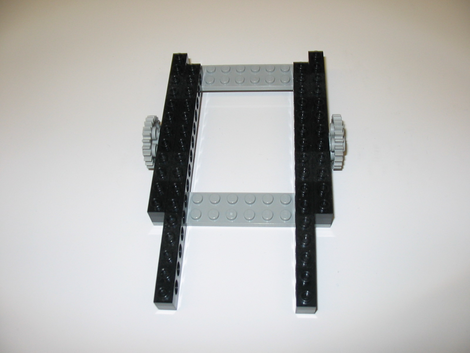
Note the 1 stud offset between the ends of the beams, and that the gears are
secured to the outer beams using the seventh hole from the rear of the
rover (the end towards the back of the picture).
Step 2
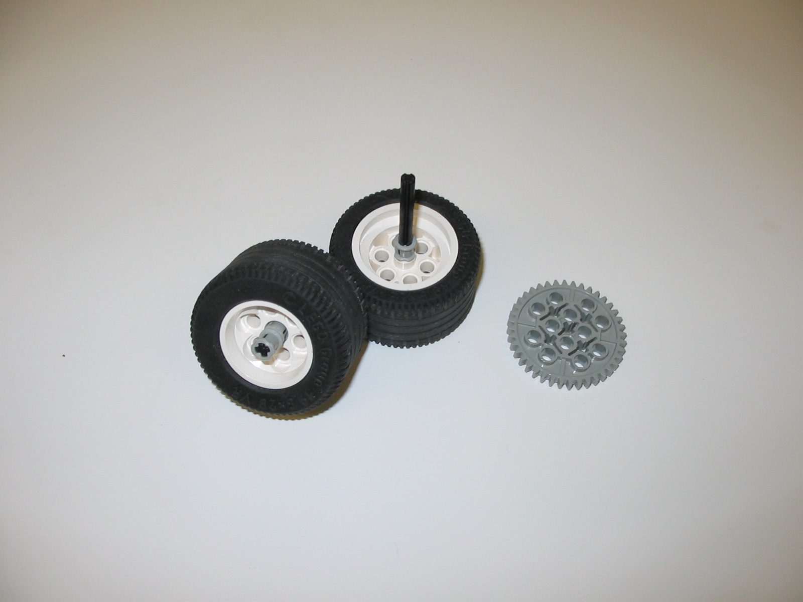
Now pick out:
- four wheels;
- four black 8-stud axles;
- four 40-tooth gears; and
- 16 grey bushings.
and combine these to obtain four wheel assemblies:
Each axle has, in order, two bushings, the wheel, another bushing,
then the gear. If the wheel is correctly oriented with respect to the axle (click on the lefthand photo to see an example of correct orientation), then when the wheel is added to the chassis
The four spare bushings you see on the right will be used to attach
the wheel assemblies to the chassis.
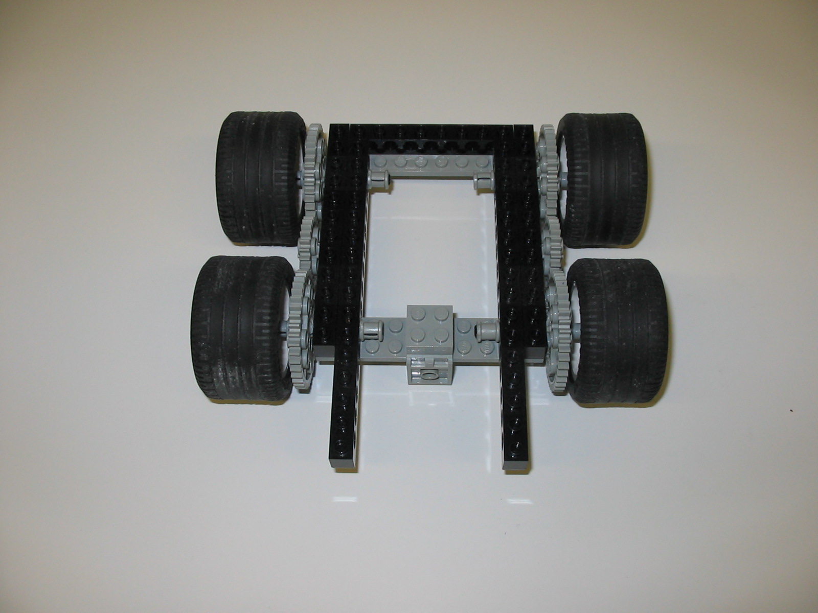
Step 3
Adding the wheels is is the next step:
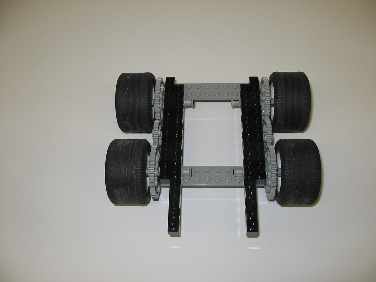
The wheels are positioned so that the gears all mesh and the extra
bushings are fitted onto the ends of the axles.
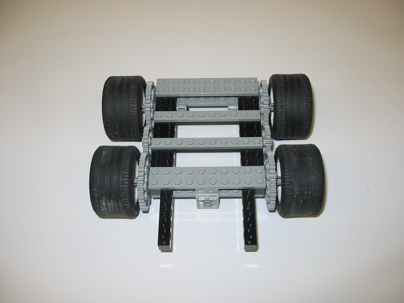
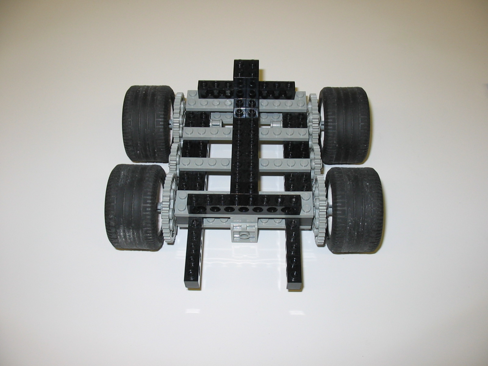
Step 4
Take:
- one black 1 x 8 beam
- one grey 2 x 2 angle plate;
- two grey 2 x 2 plates
- two grey 2 x 10 plates; and
- two grey 1 x 10 plates
Add these to the chassis as shown:
In the front, the angle plate goes on top of the 2 x 2 sandwich.
Step 5
For the next layer we need:
- two black 1 x 8 beams
- two black 1 x 10 beams
- two black 2 x 2 blocks
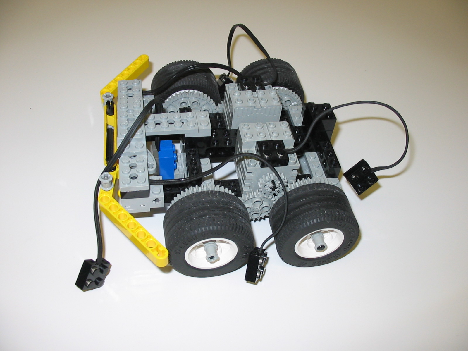
These are added as shown, with a stack of 2 x 2 blocks over the junction of
the three beams at the back of the chassis:
The motors (with connectors) can then be added, along with the light sensor:
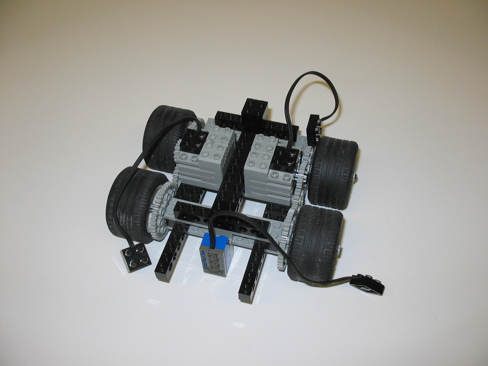
Note that each motor has a 16-tooth gear added it its axle; this
should mesh with the 24-tooth gear when the motor is in place.
Before we go any further, we need to construct the simple double bumper
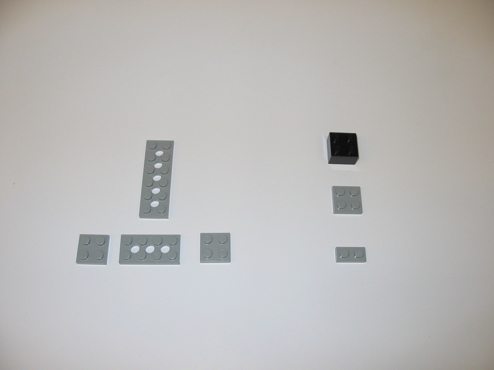
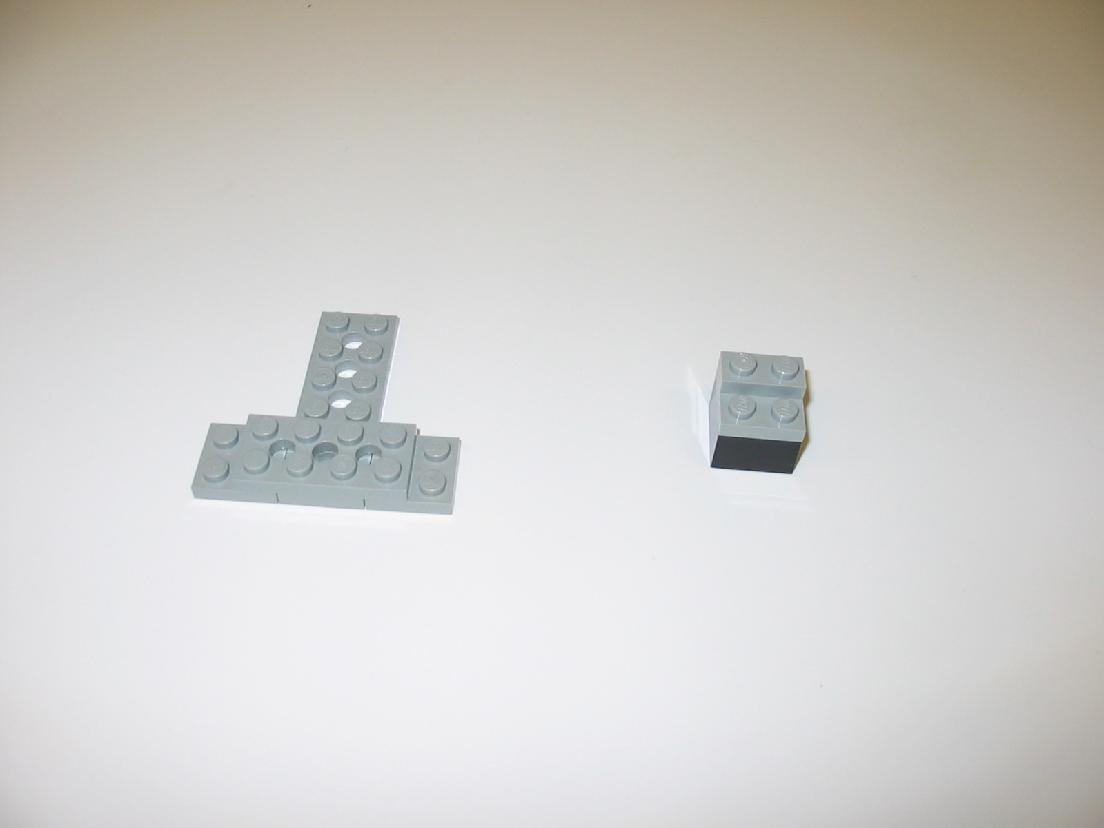
Step 6
Collect together:
- one grey 2 x 6 plate;
- one grey 2 x 4 plate;
- two grey 2 x 2 plates;
- one grey 1 x 2 plate; and
- one black 2 x 2 block.
Assemble these as shown:
and use to connect the double bumper to the chassis:
The RCX-brick can then be placed on top of the chassis, and connected
to the motors and sensors.
Connecting up
The various control programs for this robot assume that the motors are
connected to ports A and C, the touch sensors are connected to ports 1
and 3 (each is connected to the nearest port), and the light sensor is
connected to port 2.
Parts required
- four wheels (the ones that are just larger than a 40-tooth gear);
- two black 1 x 16 beams;
- two black 1 x 12 beams;
- two black 1 x 10 beams;
- three black 1 x 8 beam;
- four grey 2 x 10 plates;
- one grey 2 x 6 plate;
- one grey 2 x 4 plate;
- seven grey 2 x 2 plates;
- two grey 1 x 10 plates;
- one grey 1 x 2 plate;
- four black 2 x 2 blocks;
- one grey 2 x 2 angle plate;
- two 16-tooth gears;
- two 24-tooth gears;
- four 40-tooth gears;
- two connector pegs with axle;
- four black 8-stud axles;
- 16 grey bushings;
- two motors;
- one light sensor; and
- two short wires.